Visualizing Scales and Distances
|
1238888 |
SCENE allows visualizing dimensions and distances in the 3D view by displaying a customizable two-dimensional grid.
This tool is only available in the 3D view.
The grid is a set of visible lines that serve as a visual distance reference and can be seen as a two-dimensional ruler. The grid can be positioned anywhere in SCENE and gives a good impression of distances and scales in the point cloud. You can attach the grid to a scan point, or with one or three clicks.
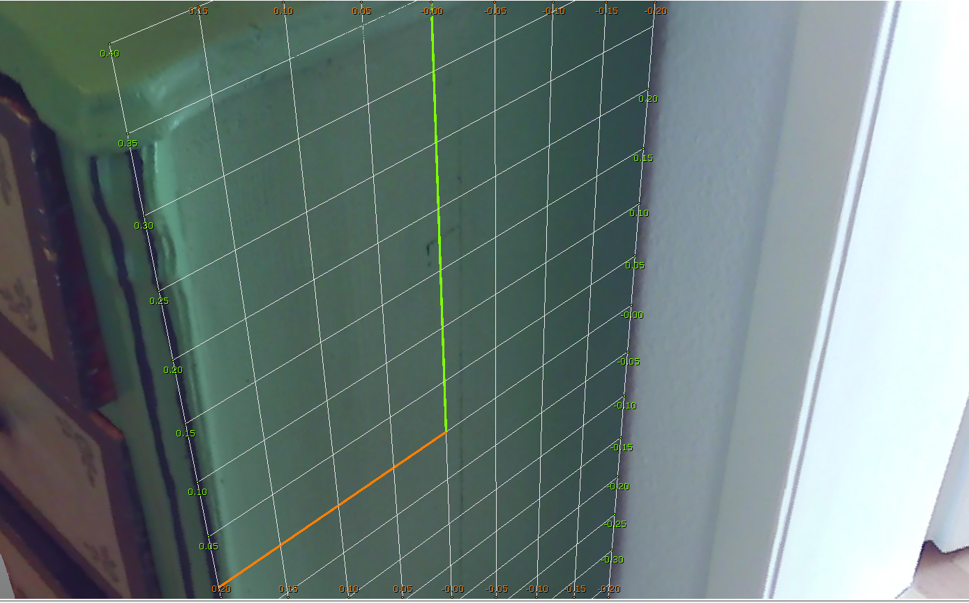
Figure 10-21 Regular grid in 3D view
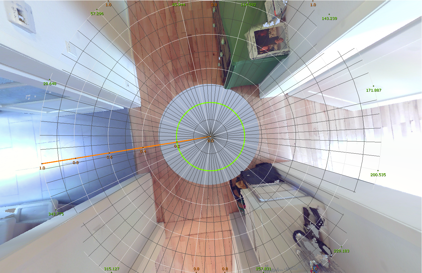
Figure 10-22 Polar grid in 3D view
Displaying and customizing the grid
-
Open the Grid dropdown menu and select Show Grid.
By default, the grid is located in the coordinate origin and lies in the XY plane. -
Then, use the dropdown menu options to make your adjustments.
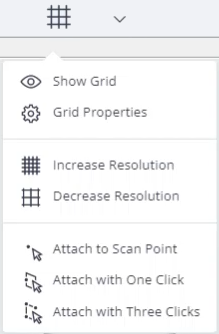
Figure 10-23 Grid dropdown menu
Grid Properties
Open the Grid Properties dialog from the Show Grid dropdown menu. The dialog has different options to set the grid properties.
Style
-
The regular grid divides the space in axially parallel and evenly spaced rectangular areas. Both scales in X and Y direction show the distance in relation to the grid’s origin.
-
The polar grid consists of concentric rings and radial dividers. The concentric rings show the distance to the grid’s origin. With the radial dividers one can estimate the angles between two points of interest.
Start/End – Define the dimensions of the displayed grid in both directions by entering a Start and an End value.
Colors – Change the color of the lines for the two directions.
Resolution – Define the resolution of the grid by changing the distance between the displayed grid lines for both directions.
Resolution
Increase the resolution of the grid by decreasing the distance between the displayed lines by a factor of 2.
Decrease the resolution of the grid by increasing the distance of the displayed lines by a factor of 2.
Tab Display Options
On this tab you can toggle the visibility of certain visible grid elements:
Direction X – x-axis (colored line)
Direction Y – y-axis (colored line)
Labels X – labeling of lines parallel to the x-axis
Labels Y – labeling of lines parallel to the y-axis
Primary Scale X – labeled lines of the grid in x direction
Primary Scale Y – labeled lines of the grid in y direction
Secondary Scale X – non-labeled lines visible at certain zoom levels in x direction
Secondary Scale Y – non-labeled lines visible at certain zoom levels in y direction.
Attach to Scan Point
Change the position of the grid’s origin. Pick a point in the SCENE and the grid’s origin will be moved to that point.
Attach with One Click
Align the grid by picking one click, if the plane has an even surface.
Attach with Three Clicks
Align the grid by picking three points, if the plane is uneven, or if you need a high accuracy. Picking three points for planes makes sense for outdoor scans, or for a scans of an old building in which floors or ceilings often are more or less curved.