Creating the Project Point Cloud
|
1238888 |
The project point cloud is typically created from all the single scans in your project after they have been processed and registered.
-
Open the scan project from the Project Overview, or by clicking the Open Project button
 in the Project toolbar.
 -
Click the Explore button in the workflow bar.
-
Click the Project Point Cloud button
 in the toolbar. A dropdown menu opens.
 -
Select Create
 .
.
Preparing your Scan Project
The resulting point cloud is about two to four times the size of your scan files
Project point cloud creation will only consider the global position of the scan points at the time of the creation. All changes to scans, clusters, or folders that are performed after the project point cloud has been created will not alter the project point cloud. This will lead to an inconsistency between the point cloud and the traditional scan-based data of the scan project. For this reason, we recommend creating the project point cloud after you have completed the registration.
You can, of course, change your registration at any time, even if a project point cloud already exists, but be aware that the project point cloud will not have these changes applied until it is updated or recreated.
Project Point Cloud Creation Settings
After you have initiated the project point cloud creation, the point cloud settings dialog shows up:
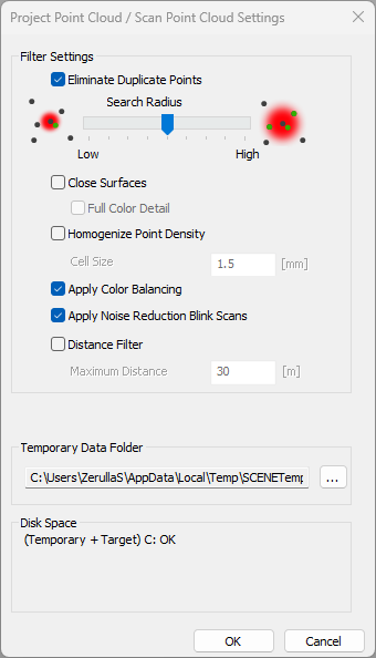
Figure 10-61 Create project point cloud settings
Filter Settings
For the creation of the project point cloud, the following point filters are available. Each of these filters will reduce the overall point count by eliminating different types of (unwanted) points.
Eliminate Duplicate Points
The filter removes duplicate points that always exist when points are recorded from several different scanner positions. Overlapping areas can be optimized by removing some of the duplicate points. This filter can improve the visual quality of your project point cloud significantly while reducing overall point count and therefore improving interactivity and loading times of the point cloud.
Points are considered duplicates of others when they were recorded from different scanner positions and their 3D positions are similar. The actual distance threshold for duplicate points depends on point-to-scanner distances. The farther from the scanner a point is recorded, the “larger” we consider this point to be, because the farther a point is recorded, the greater the spatial distance to its neighbors.
The filter is configured to always keep the highest quality point. Higher quality means smaller distance to the scanner position. If two points are considered duplicates of each other, the point with the greater distance – and therefore lower quality – is dismissed. Only the higher quality point is added to the project point cloud.
When creating a project point cloud from a project that contains both, laser scanner scans and handheld scans, all points are considered. Usually, handheld scanner points are used only where no laser scanner points are available.
With the Search Radius slider you can adjust the distance threshold for point elimination. The default setting should be sufficient for almost all scenarios.
Adjust the Search Radius slider to the right to enlarge the search radius and increase the number of eliminated points. This may help to reduce point count when your registration is not very accurate (for example when using natural targets only).
Adjust the Search Radius slider to the left to reduce the number of eliminated points. This can be useful if too many points have been deleted by this filter in previous point cloud iterations.
Close Surfaces
Select this checkbox if you want to have additional points interpolated between original scan points, to create a denser impression of the surfaces. The color or gray value of these additional points will also be interpolated.
Scans captured using FARO handheld scanners are interpolated immediately after they are captured (if the appropriate option was enabled during capture). No additional interpolation is performed for these data sets during project point cloud creation. Nevertheless, you need to select this option to get a closed surface representation of your data. If you don’t, points of handheld scans are stored with smaller sizes.
Full Color Detail
Select this option if the color of the points shall be retrieved from the laser scanner's high resolution camera images. Moreover, additional even smaller points are interpolated to transfer the color information from the camera images into the point cloud. By using the images from the camera images, smearing effects are reduced and more color details are visible in the project point cloud.
The time needed for the interpolation and the creation of the point cloud will greatly increase. The files will need much more disk space.
Homogenize Point Density
This filter balances the density of points within the point cloud by reducing the number of points in areas where the average target density is exceeded. This is especially the case close to scanner positions, where the point density is particularly high or in areas where two or more scans overlap. By reducing the total number of points in the point cloud, less hard disk space is required and the performance of the point cloud visualization is increased, while preserving the overall visualization quality.
The achievable rate of data reduction is highly dependent on the input data. Outdoor projects with little overlap between scans will benefit less than densely scanned indoor projects where a data reduction of 25% and more can be achieved with hardly any perceivable loss of visualization quality.
Cell size
You can adjust the cell size of the existent homogenization feature. The standard value of 1.5 mm was empirically chosen so that no band artifacts emerge. The unit of the maximum distance is adapted according to the setting of the small standard units. The homogenization and Close Surfaces are mutually exclusive, which means that setting the Close Surfaces will unset the homogenization checkbox and vice versa.
Apply Color Balancing
A typical effect seen in real world laser scanning projects is that the overall perception of color may not always be consistent across colored scans. This effect can have two different reasons:
-
The internal camera of the FARO Focus Laser Scanner performs white balancing on a per-scan basis. As a result, the internal camera may choose to apply a different white balancing at different scan positions, given that the lighting conditions vary. For example, the scanner is set up in a room illuminated by neon lights as opposed to natural light when scanning outdoors.
-
While carrying out a scanning project, lighting conditions may vary over time. For example, when the project starts in the morning and is completed in the evening (or even on another day).
This effect may especially become apparent when such differently colored scans are combined into a project point cloud and visualized together as shown in the following figure:
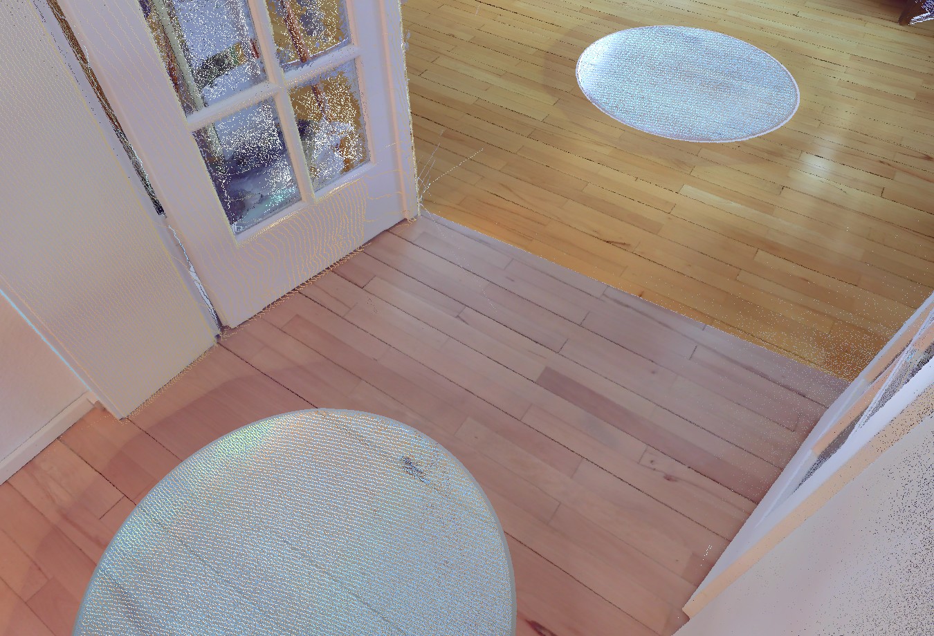
Figure 10-62 Inconsistent color of a floor due to scans taken under varying lighting conditions.
When enabled, the color balancing filter minimizes the color contrast between scans in the project point cloud and results in a more homogeneous overall perception of color as shown in the following figure:
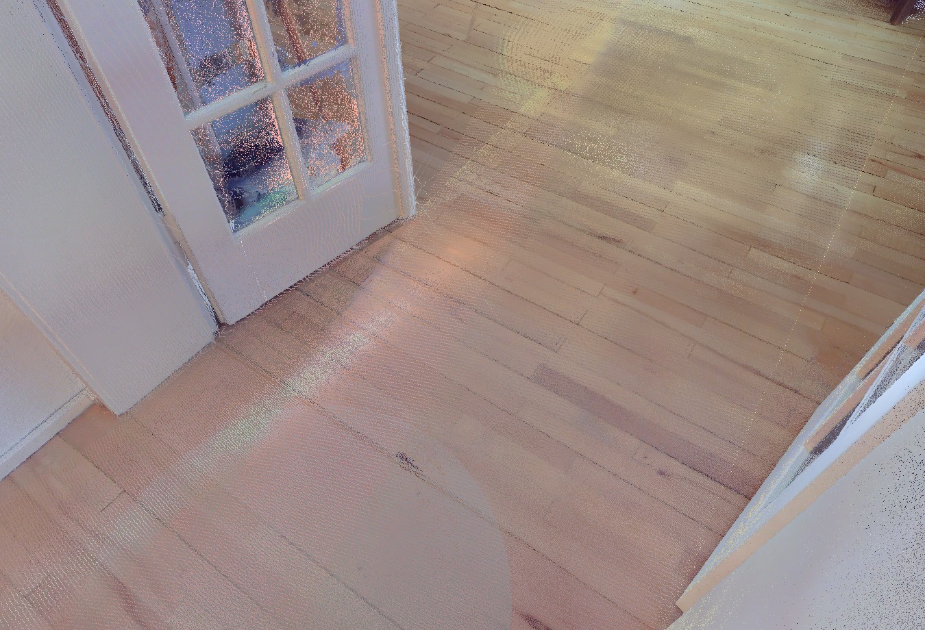
Figure 10-63 Significant reduction of color inconsistencies by applying color balancing
Apply Noise Reduction Blink Scans
If activated, the project point cloud is improved by reducing surface irregularity/noise and removing outlying data points. Note that this setting only works for Blink scans.
Distance Filter
If this checkbox is set, all points which are more than Maximum Distance units away from the associated scanner position will not be used to create the project point cloud. This filter can be used to restrict the point cloud to the more precise near the area of the scanner. For example, if you scan a windowed room, you can now ignore most outside stray points, which are probably bad, because they were scanned through the window glass. The unit of the maximum distance is adapted according to the setting of the standard units.
Temporary Data Folder
During the project point cloud creation process all scans in the project will be loaded successively; their point data will be processed and saved as temporary data. This temporary data will be stored inside the temporary data folder. Do not delete, move or copy any of these files during the point cloud creation process or the process might fail. The temporary data will be deleted automatically after the process is complete.
Section Disk Space shows if there is enough free space on the hard disk used for the temporary data and the (target) hard disk used for saving the final point cloud data. The target hard disk is the disk on which the scan project data is stored.