Text
Use Text commands to add text-based elements to your drawing.
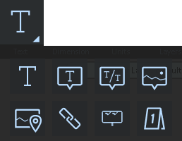
The following text elements are available:
 Text Label
-
From the Home ribbon, click the Text drop-down arrow and select Text.
-
Move the cursor onto the diagram so the text label is visible.
-
Complete options in the Text tool panel.
-
Click Back.
-
Click the location in the diagram at which to place the text box.
-
Use the grips to make adjustments.
Text Tool Panel
Use the following options to configure the text:
 Text Color Text Color
|
Select the color of the text. | |
| Background color | Select the color of the text. | |
 Layers Layers
|
Open the Layer Manager. Assign the text box to a new or existing layer. | |
 Reset Reset
|
Reset the tool to its default settings. | |
| Match Properties | ||
| Formatting tools | ||
| Text | Type the desired text string. Use the Enter key to add multiple lines of text. For enhanced text editing options, click the paragraph symbol to the right of the Text field to open an editor. | |
| Height | Adjust the height of the text box. | |
| Position and Orientation | X, Y, Z Values - Lists X, Y, Z values, which you can change by entering values or by using the dial arrows. Yaw - Adjust the sideways position of the text box. Pitch - Adjust the vertical facing position of the text box. Roll - Rotate the text box. |
|
| Match Properties | Use the Match Object tool to replicate and re-use the properties of a selected object. See Match and Clone Objects. | |
| Text 1x | Enter the text to display on the top line. | |
| Text 2x | Enter the text to display on the bottom line. | |
| File or URL |
Browse to, and select a file or video, or paste a URL address. You can test the link by clicking Launch Link . |
|
| Bubble Size | Enter the size of the bubble box (in feet). | |
| Fill | Fill the background of the text box with a color. Select a color from the pallet. | |
| Arrow | Display or hide an arrow. From the palette, select the color for the arrow. | |
| Rectangle |
Change the bubble shape to a rectangle.
|
|
| Ignore Lighting | For the text bubble, ignore any lighting effects assigned to the drawing. | |
| Units | Select the unit of measure from the drop-down list, or leave the option at Automatic to use the default unit setting. | |
| Settings | ||
| Axes | Set the axes, and the yaw, pitch, and roll. | |
| Text Settings/Border | Select the text control from the drop-down list. | |
| Font | Select the display font. | |
| Fill | Select a fill color for the text box. | |
| Border | Add a border to the text box. Select a color from the pallet, and select whether to use rounded corners. | |
| Padding |
Add padding between the text and the edges of the text box.
|
|
| Rounded | Round the corners of the text box. | |
| Stretch Text | ||
| Show Drop Shadow | Add a drop shadow to the text. Adjust the drop shadow by entering X and Y coordinates. | |
| Facing Camera | Have the text display, no matter where the camera is placed. | |
| Include in DZR Annotation | ||
| Leader Arrow Settings | Configure options for a leader arrow. | |
| Leader Position | Select the coordinate position for the leader arrow. | |
| Show Leader Arrow | Show or hide the leader arrow. Select the color palette to change the arrow's color. | |
| X, Y, Z | Adjust the axes for the leader arrow | |
| Set Leader Thickness | Adjust the thickness of the arrow stem. | |
| Set Arrow Size | Adjust the size of the arrow point. | |
| Flat Arrows | Adjust the style of the arrow point. |

 Text Bubble
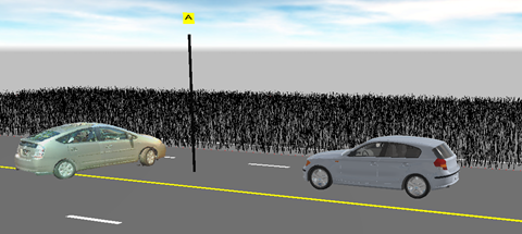
Use a text bubble to label evidence, identify witness/photo locations, etc.
To create a text bubble:
-
On the Home ribbon, click the Text drop-down arrow.
-
Click Text Bubble.
-
Click the location in the diagram at which to place the text bubble. The first click sets the point of the arrow, move the cursor to the bubble placement location and click a second time.
-
Press Enter to add one text bubble, or use the 2-click process to add multiple text bubbles. Press Enter when you are done.
-
Configure options for the Bubble Label text box.
Bubble Label Tool Panel
|
Color
|
Select the color of the text bubble. | |
| Text color | Select the color of the text. | |
|
Layers
|
Open the Layer Manager. | |
|
Reset
|
Reset the tool to its default settings. | |
| Match Properties | Use the Match Object tool to replicate and re-use the properties of a selected object. See Match and Clone Objects. | |
| Text 1x | Enter the text to display on the top line. | |
| Text 2x | Enter the text to display on the bottom line. | |
| File or URL |
Browse to, and select a file or video, or paste a URL address. You can test the link by clicking Launch Link . |
|
| Bubble Size | Enter the size of the bubble box (in feet). | |
| Fill | Apply a color fill to the bubble. | |
| Arrow | Display or hide an arrow. | |
| Rectangle |
Change the bubble shape to a rectangle.
|
|
| Ignore Lighting | For the text bubble, ignore any lighting effects assigned to the drawing. | |
| Units | Select the unit of measure from the drop-down list, or leave the option at Automatic to use the default unit setting. | |
| Settings | ||
| Axes | Set the axes, and the yaw, pitch, and roll. | |
| Text Settings | Select the text control from the drop-down list. | |
| Font | Select the display font. | |
| Text Color | Select the text color. | |
| Bold | Bold the text. | |
| Italic | Italicize the text. | |
The following options are available:
Text 1x - Type the text for the top line.
Text 2x - Type the text for the bottom line. Numbers entered in the Text 2 field automatically increment for each new bubble.
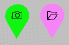
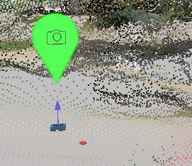
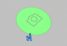
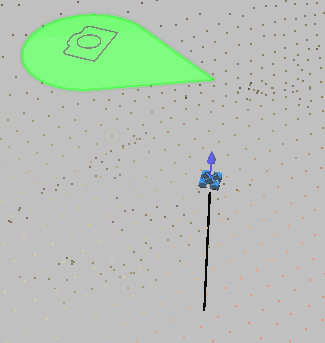
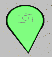
 Bubble Picture
Use bubble pictures to add additional photos to the map image.
 File Reference
Use File Reference to insert an reference marker which you can double-click to display a file such as an image, video, PDF, File references and their associated files export to Zone2Go projects.
| Color |
Select the color of the file reference bubble. You may want to use different colors for various file types.
|
|
| Icon color | Select the color of the icon that is located within the file reference bubble. | |
|
Layers
|
Open the Layer Manager. | |
|
Reset
|
Reset the tool to its default settings. | |
| File |
Browse to, and select a file or video to attach. If the file is a panoramic image, select Is Pano Image. |
|
| Open File | Click Open File to view the file. | |
| Open Folder | Open the folder that contains the selected file. | |
| Toggle Standing |
Display the file reference marker vertically. This setting carries over to Zone2Go.
|
|
| Settings | Adjust position and size settings for the marker. | |
| X, Y, Z | Adjust positional coordinates | |
| Yaw, Pitch, Roll | Adjust the rotational axes of the marker. | |
| Size, Icon Scale, Icon 3D Offset | Adjust the size of the marker, the size of the icon that appears within the marker, and the icon's offset. | |
| Custom Size |
Enable this option to apply a custom size different from other file references in the drawing. |
|
| Circle Mode |
Display the file reference marker as a circle.
|
|
| Unlit | Turn on/off shadow and lighting effects for the marker. | |
| Facing Camera | Set the marker to always face the camera. | |
| Pole |
Attach the file reference to a pole to offset the marker from the ground..
|
|
| Show Pole | Display or hide the pole. | |
| Pole Color | Select the pole color. | |
| Pole Height | Select the pole height. | |
| Pole Offset | Select the pole offset from the marker. | |
| Pole Size | Select the width. | |
| Outline |
Add an outline to the marker.
|
|
| Show Outline | Show or hide the marker's outline. | |
| Outline Color | Select the outline color. | |
| Outline Thickness | Select the outline thickness. | |
 Web Link
Use the Web Link command to add a marker that includes an Internet link.
To insert a hyperlink:
-
On the Home ribbon, click the Text command drop-down arrow.
-
Click the Hyperlink command.
-
The Web Link tool panel opens.
-
Enter a name for the web link.
-
Enter the web address in the URL field.
-
Click the location in the drawing on which to place the marker.
-
Open the link by double-clicking the marker, test the marker by clicking Launch Link in the tool panel.
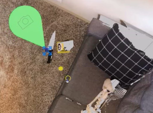
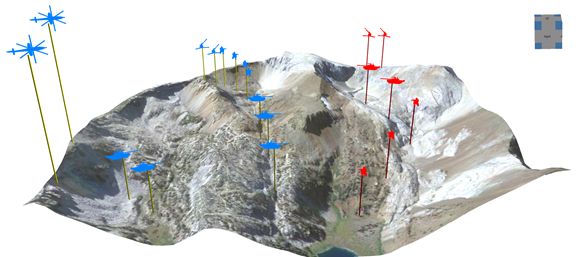
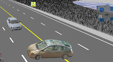
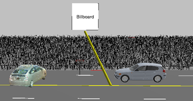
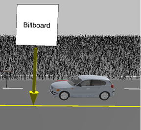
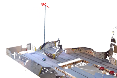
 Billboard
Select any object, such as a text, symbol, or 3D model, and elevate it in the drawing so that it is always visible. This allows you to annotate the important parts of your drawing with any object type.
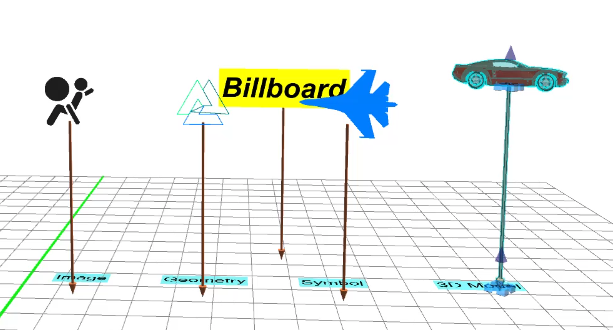
Billboards are also useful for identifying important subject areas in large images with terrain.
To apply the Billboard command to an object:
-
Select an object.
-
Right click the object and select the Billboard command (for symbols and models), or select the
command from the Text dropdown. -
Use the grip to adjust the height.
-
Click Edit Object to change the settings for the object selected as the billboard.
-
Make adjustments in the Billboard tool panel.
-
Add other billboards that you think are necessary to call out in the drawing.
Billboard tool panel
 Layer Layer
|
Add the billboard to a new or existing layer. |
 Arrow and Pole color Arrow and Pole color
|
Use the color picker tool to select the color for the arrow and the pole. |
|
Reset
|
Reset the tool to its default settings. |
| X, Y, Z Values | Displays X, Y, Z values, which you can change by entering values, or by using the dial arrows. |
| Yaw, Pitch, Roll |
Adjust: Yaw Pitch
Roll
|
| Scale |
Adjust the size of the billboard. This is useful for sizing the billboard so that it displays clearly, depending on the size of your point cloud, map, or other aspects of the drawing. |
| Show Post |
Display or hide the post for the billboard. You can adjust the size and offset of the post.
|
| Post Vertical |
Enable this option to keep the post vertical under the billboard. Disable this option to offset the base of the post with the grip.
|
| Show Arrow |
Display an arrow at the base of the post.
|
| Post Length |
Adjust the length of the post.
|
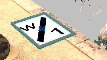
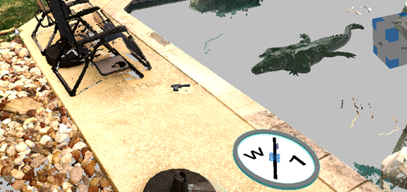
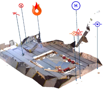
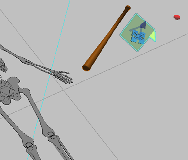
 Evidence marker
Use the Evidence marker tool to add an evidence marker to the diagram.
To insert an evidence marker:
-
On the Home ribbon, click the Text command drop-down arrow.
-
Click Evidence Marker.
-
Click the area in which to place the evidence marker.
-
Configure options in the Evidence Marker tool panel.
-
Use the grips to make positional/sizing adjustments.
Evidence Marker tool panel
| Text | Type the text to display in the evidence marker. Depending on the length of the text string, you may have to adjust the size of the evidence marker. |
| File or URL | Enter a file to open a file when the evidence marker is clicked, or enter a URL to open a web link. Select Launch Link to test the web link. |
| X, Y, Z Values | Displays X, Y, Z values, which you can change by entering values, or by using the dial arrows. |
| Length | Adjust the length. |
| Width | Adjust the width. |
| Height | Adjust the height. |
| Background color | Select a background color from the color palette. |
| Text color | Select the text color from the color palette. |
