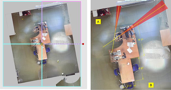
Clipping Boxes
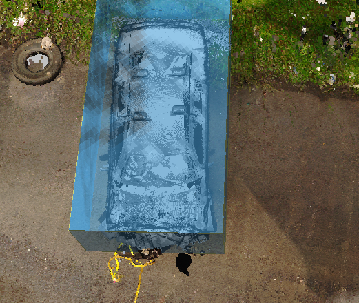
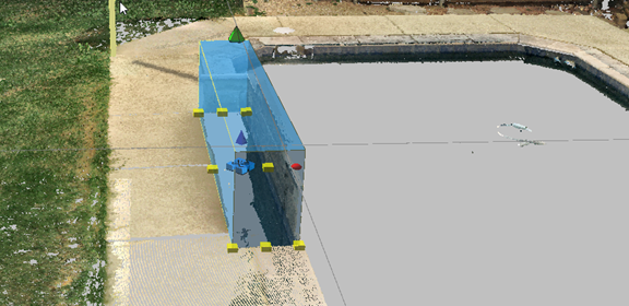
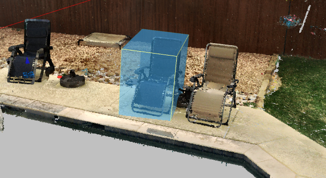
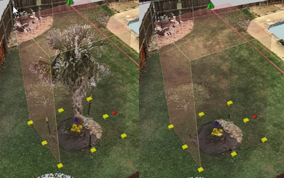
Use Clipping Boxes to hide or obscure content within the clipping box or from areas surrounding the box. Points are hidden, but not deleted from the point cloud. For example, you can hide the roof of a building so that you can see inside from the roof view, or hide treetops to reveal the street below. You can also hide people or objects. You can create multiple clipping boxes.

 Adding a Clipping Box
To add a clipping box to your point cloud scene:
-
Turn off snaps.
-
From the Point Cloud ribbon, click
 Add Box. The Clipping Box tool panel displays.
 -
Click in the point cloud to establish the first corner of the clipping box.
-
Click again to establish the box length.
-
Click again to establish the box width.
-
Click again to establish the box height.
-
Use the grips to move, resize or rotate the clipping box.
-
Modify the clipping box in the Clipping Box tool panel.
-
View and manage all of the clipping boxes in the Clipping Box Manager.
Clipping Box Tool Panel
The Clipping Box tool panel provides precise control of clipping box properties.
| Display Options | ||
| Hide Inside |
Hide the objects inside the clipping box. Turn the option off to hide everything outside the box.
|
|
| Obscure Inside |
Pixelate the objects inside the box. Use the slider to adjust pixelation. This is often used to obscure bodies or other private objects that you want to obscure.
|
|
| Box Disabled | Enable this option to disable the Hide Inside and ObscureInside controls. Deactivate to resume Hide and Obscure settings. | |
| Clipping box coordinates | Set size, location, and rotational coordinates for the clipping box. | |
| Settings | ||
| Snap Disabled | When this option is enabled, the clipping box does not snap to anything. Disable this option to have the box snap to points in the point cloud, or to objects. Enabling this option is helpful if the cloud is well above the ground plane. Disable it to snap the clipping box to an object or area, such as a tabletop. | |
| Outline | Show the clipping box's outline, but hide the fill. | |
| Color | Click to select a clipping box color. Use the slider to adjust the transparency. | |
| Tools | ||
|
|
Select Points | Highlight points to use for point cloud models. This is not required for creating a model, but it visually identifies the points in a potential model. |
| Create Model |
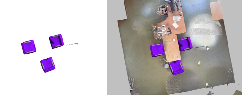
Create a model from the point cloud that is within the clipping box. For example, you can create models from objects in the point cloud that you want to duplicate in the drawing, or use in other drawings.
|
|
| Create Ortho Image |
Use a clipping box to create a top down ortho image. These images are created with tiled, high-resolution, scaled images. This is helpful for quick 2D diagramming and dimensioning. You can also print 2D point cloud images along with the diagram. Ortho images are less cumbersome to work with than point clouds and they may be sufficient for your project.
When you create the ortho image, you are prompted to name the project (if you have not already done so). The software places the ortho image on the ground plane, inline with the point cloud. To see the image, hide the point cloud, select the image, and then move the image to another area. Select the ortho image to see the tiles. The tiled images are stored in the project folder.
|
|
| Setup 2D View Point Cloud Display | ||
| Density-based Ortho Map |
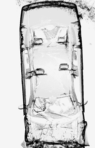
Create an density ortho map outline of the point cloud data based on the density of points that are vertically in-line. For example, walls have many points stacked on top of each other. This tool helps you generate a clear outline of a building floorplan or vehicle. For more information, see Creating a Density-Based (Ortho) Map From a Point Cloud.
|
 Clipping Box Manager
Use the Clipping Box Manager to view and edit all of the clipping boxes in the drawing.
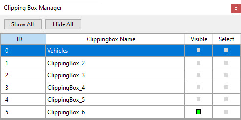
Check or uncheck Visible to show or hide the clipping box. Use Show All or Hide All to show or hide all of the clipping boxes.
Click Select to display the tool panel for a clipping box.
Creating a Density-Based (Ortho) Map From a Point Cloud
Create an ortho density map outline of the point cloud data based on the density of points that are in-line vertically. For example, walls have many points stacked on top of one another. This tool generates a clear outline of a building floorplan, or a vehicle.
1. Draw a clipping box around the section of the point cloud for which you want to generate an ortho image.

1. From the Clipping Box tool panel, set Display Options to Hide Outside.
2. From Clipping Box > Tools, click Ortho Density Map. The image opens in a dialog box that includes options for viewing and adjusting the ortho density map.
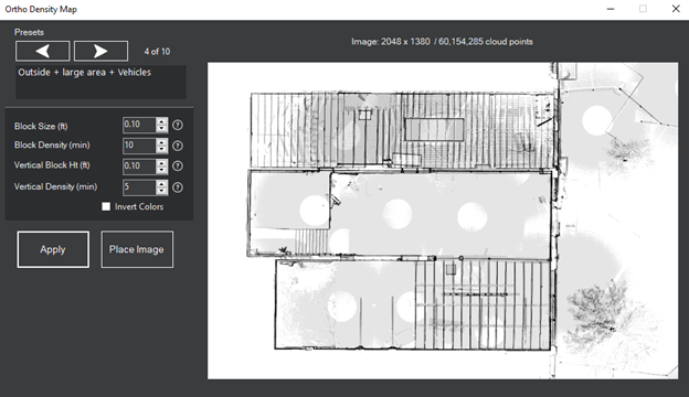
4. You can adjust the following settings:
| Samples |
View the preset samples and select the one that helps you get closest to your desired display. After you select a preset, give the program time to regenerate the image. When you find the desired preset , you can make incremental changes under Advanced Settings.
|
| Advanced Settings | |
| Block Size (ft) | The size of the smallest ‘square’ block top down where points will be grouped/counted together. A smaller size creates finer lines, but it also increases memory use and processing time. |
| Block Density (min) |
Minimum number of points in block needed to be included. Cells with less points than this value will be ignored. When you use Vertical Block Height and Vertical Block Density together, they are considered a “fine filter” and affect the image's contrast |
| Vertical Block Height (ft) | In each cell Vertical ‘stacks’ on the “top down” blocks (side view). |
| Vertical Density (min) | The minimum number of points to include in a vertical block. Cells with less points than this value are ignored. |
| Density Image Preview | Preview the results based on the settings. |
| Apply | Update the Density Image Preview after you change advanced settings. |
| Place Image | Save and load the ortho density map. If you click Yes to load the image, it is placed directly on the point cloud at the exact location from which it was generated. |
