Positioning the Point Cloud
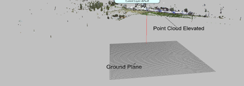
In many cases, you will need to center the point cloud within the coordinate system. This is because, depending on your scanner settings, your point cloud may have been scanned anywhere above or below the ground level (elevation/Z= 0).
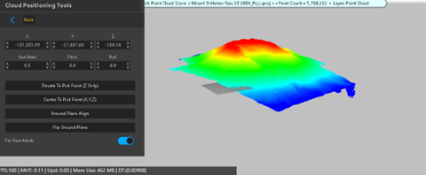
You can manually adjust the position and orientation of the point cloud using the edit boxes. Alternatively, you can use one of the following tools to automatically adjust the point cloud.
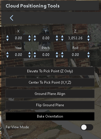
Elevate To Pick Point (Z Only) - Select a point on the point cloud to adjust to Zero (the ground plane).
Center To Pick Point (X,Y,Z) - Adjust the point cloud so the selected point becomes (0,0,0) in the coordinate system.
Ground Plane Align - Select three points on the point cloud to align with the ground plane.
Flip Ground Plane - Reverse the “up” direction of the selected ground plane alignment.
Bake Orientation - Select this option to bake the orientation into the underlying point cloud project. You will need to recreate the point cloud project. Existing clipping box positions will be altered.
Far View Mode
For performance and accuracy, rendering is limited to a certain distance from the camera. This is called a far plane. Sometimes the point cloud size exceeds the limit, or the camera was moved to a position outside of the range. Standard Far Clipping plane for point clouds is roughly 3000 feet. Far View Mode is roughly 15,000 feet.
The following image shows Mt. St. Helens (scaled down) captured from drone Lidar and converted to an LSProj, with Height Map enabled in the color settings.
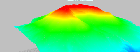
Far Clipping occurs here:
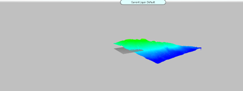
Enable Far View Mode to extend the far clipping plane.
