FARO Laser Line Probe Compensation
|
1238888 |
After you complete the installation of the FARO LLP and the standard probe, this system of probes must be compensated. Compensation requires measuring the FARO Compensation Plate with a standard probe and the LLP from five different positions.
When necessary, clean the top and bottom lenses with the cloth from the LLP case. Dirt and grease on either lens can cause poor results.
-
Open CAM2 and on the Devices tab, click Device Control Panel. On the Device Control panel, click Probe Management to show the Probes dialog box.
-
Choose a standard ball probe, 6 mm or 3 mm by clicking on the probe name.
Figure 10-4 Compensating the Standard Ball Probe
Do Not use probe extensions when compensating the LLP.
-
Calibrate the standard ball probe using the single hole compensation method.
-
Choose the Laser Probe (LLP) probe by clicking on the probe name.
Figure 10-5 Compensating the LLP
Ensure that High Accuracy Mode is disabled during compensation. See FARO Laser Line Probe Settings.
-
Choose Plane Compensation.
-
Select or clear the Guidance check box.
Guidance monitors the position and angle of the LLP during the compensation process and ignores any points outside optimal position and angle.
-
Click Measure Plane or Compensate LLP with Previous Values to use the previously measured plane.
-
The laser turns on and the laser beam is visible unless you are measuring the plane. After you successfully measure the plane, the laser turns on and the laser beam is visible.
-
Plane Compensation
Calibrate the FARO FARO Technologies, Inc.. You will digitize the FARO Compensation Plate, once with the ball probe, and then from five positions with the LLP.
-
Digitize the white area of the FARO Compensation Plate with the ball probe.
-
Touch the white surface with the ball probe and press the green Front button.
-
Digitize nine points on the white surface.
Digitize each point near an edge of the surface to avoid marring the middle of the surface. Digitize a single point in the center of the plate.
-
Pull the probe away from the surface and press the red Back button.
The flatness of the white surface is calculated and the results are displayed in the dialog box. If the results Fail, click Restart Plane to redigitize the white surface. Click OK to continue.
Figure 10-6 Measuring the Compensation Plate with the Ball Probe
Avoid touching the lenses. When necessary, clean the top and bottom lenses with the cloth from the case. Dirt and grease on either lens can cause poor results.
-
-
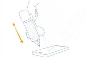
Click Start Compensation. You will need to collect 75 lines at five different positions around the FARO Compensation Plate. The 15 lines at each position require you to move the LLP completely through the operating range - from the near field to the far field. At each position you may need to twist the LLP so the laser line projects across the plate in the same direction.
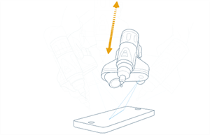
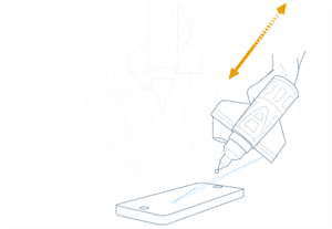
Figure 10-7 Measuring the Compensation Plate with the LLP
Position #1 - Start on one side of the compensation plate.
-
Aim the laser line at center of the white surface at a 45° vertical angle. Digitize the white area of the FARO Compensation Plate with the FARO Laser Line Probe from the near range to the far range. You must collect 15 scan lines to continue.
-
Aim the laser line at the middle of the white surface. Twist the LLP so the entire line is projected onto the white surface.
-
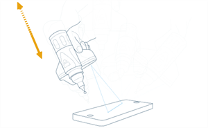
Move the LLP until the laser is too close to the plate
 .
. -
Press and hold the green Front button and move the LLP away from the plate along the 45° vertical angle while pointing to the center of the white surface. Keep moving until you are too far from the plate.
For each position, you can start too far from the plate and move until you are too close to the plate.
-
Position #2 - Rotate the LLP 90° around the compensation plate.
-
-
Aim the laser line at center of the white surface at a 45° vertical angle. Digitize the white area of the FARO Compensation Plate with the FARO Laser Line Probe from the near range to the far range. You must collect 15 scan lines to continue.
-
Aim the laser line at the middle of the white surface. Twist the LLP so the entire line is projected onto the white surface in the same direction as in Position #1.
-
Move the LLP until the laser is too close to the plate
. -
Press and hold the green Front button and move the LLP away from the plate along the 45° vertical angle while pointing to the center of the white surface. Keep moving until you are too far from the plate.
-
Position #3 - Rotate the LLP 90° around the compensation plate.
-
-
Aim the laser line at center of the white surface at a 45° vertical angle. Digitize the white area of the FARO Compensation Plate with the FARO Laser Line Probe from the near range to the far range. You must collect 15 scan lines to continue.
-
Aim the laser line at the middle of the white surface. Twist the LLP so the entire line is projected onto the white surface in the same direction as in Position #1.
-
Move the LLP until the laser is too close to the plate
. -
Press and hold the green Front button and move the LLP away from the plate along the 45° vertical angle while pointing to the center of the white surface. Keep moving until you are too far from the plate.
-
Position #4 - Rotate the LLP 90° around the compensation plate.
-
-
Aim the laser line at center of the white surface at a 45° vertical angle. Digitize the white area of the FARO Compensation Plate with the FARO Laser Line Probe from the near range to the far range. You must collect 15 scan lines to continue.
-
Aim the laser line at the middle of the white surface. Twist the LLP so the entire line is projected onto the white surface in the same direction as in Position #1.
-
Move the LLP until the laser is too close to the plate
. -
Press and hold the green Front button and move the LLP away from the plate along the 45° vertical angle while pointing to the center of the white surface. Keep moving until you are too far from the plate.
-
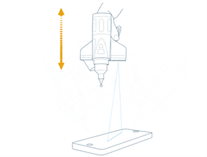
Position #5 - Directly above the compensation plate.
-
-
Aim the laser line at center of the white surface. Digitize the white area of the FARO Compensation Plate with the FARO Laser Line Probe from the near range to the far range. You must collect 15 scan lines to continue.
-
Aim the laser line at the middle of the white surface. Twist the LLP so the entire line is projected onto the white surface in the same direction as in Position #1.
-
Move the LLP until the laser is too close to the plate
. -
Press and hold the green Front button and move the LLP away from the plate while pointing to the center of the white surface. Keep moving until you are too far from the plate.
-
The digitized compensation points then calculate and the Compensation Status updates. If the probe passes, the current date and time is added to the probe information. Click Save and Exit to complete the compensation.
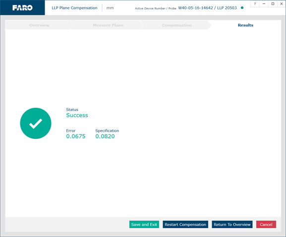
Figure 10-8 Laser Line Probe Compensation Results
You now have two probes to digitize your part. Use the Probe Management command to switch between the standard ball probe and the FARO Laser Line Probe.
If you remove the LLP, you must re-calibrate it again to guarantee the accuracy of the measurements.
You can view the details for all probe compensations by clicking View All.
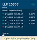
Figure 10-9 Probe Compensation List
-
