Hardware Controls and Indicators
|
1238888 |
The uses the green Front and red Back buttons and the Handle LEDs.
Buttons
Use the buttons on the
-
Use the green Front button to start data collection. Points are only sent to the computer when the laser is in range. Once you start collecting data, press the green Front button again to pause.
-
Use the red Back button to end any measurement command.
LED
The Handle LED indicates the distance to the target object from the LLP. Remember, data is only sent to the computer when the LLP is in range.
-
 Out of Range (Red LED). The LLP is too close to or too far away from the part.
 -
 Center Range (Green LED) The LLP is in the center of the range.
 -
 Near Range (Yellow LED) The LLP is in range, closer to the part.
 -
 Far Range (Yellow LED) The LLP is in range, farther from the part.
Additionally, the software uses the Range Finder Dialog Box dialog box to show the distance and position from the LLP to your part.
Range Finder
The Range Finder is an additional red cross hair that projects with the blue laser line to show you the distance from the LLP to the surface of your part.
The LLP camera does not record this cross hair.
When the probe-to-part distance is in the middle of the range, the center of the cross hair and the laser line are together.
As the distance increases or decreases, the cross hair moves away from the laser line.
|
Left as the LLP moves farther from the surface. |
Right as the LLP moves closer to the surface. |
When the LLP is out of range, the cross hair and the laser line no longer touch.
You can switch the Range Finder off in the FARO LLP Control dialog box. See FARO Laser Line Probe Settings.
Range Finder Dialog Box
The FaroArm Manager software has a Range Finder dialog box. This dialog box graphically displays the probe-to-part distance and the area of the laser line that the camera is processing.
|
|
|
||
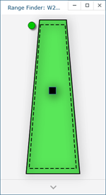
When the LLP is within the operating range, the center of the target displays as a small box in the Range Finder dialog box, see Figure 10-1
The box moves as the LLP moves:
-
Up - as you move the LLP closer to your part
-
Down - as you move the LLP farther from your part
-
Left - the right side of the line is in range
-
Right - the left side of the line is in range
The target box changes color:
-
Green - all of the laser is in range
-
Orange - some of the laser is in range
-
Red - none of the laser is in range
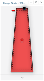
When the LLP is outside of the operating range, the target box moves to a side of the Range Finder dialog box and an arrow in the center of the dialog box points to the target box, see Figure 10-2
If the LLP is set to an Automatic exposure algorithm, there is an additional symbol in the upper left corner of the Range Finder dialog box. The symbol changes describes the exposure:
-
Red Minus Sign (-) - low exposure
-
Green Circle (O) - good exposure
-
Red Plus Sign (+) - high exposure
Details
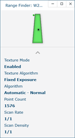
Click the arrow at the bottom of the Range Finder dialog box to view the current scanning details and LLP settings.
|
|
|
Figure 10-3 LLP Prizm details |
