Probe Management
|
1238888 |
Create, edit, select, compensate, and check, each Kinematic Probe Adapter and Probe Tip combination for use with the 6Probe . Kinematic Probe Adapters that have been installed to the current 6Probe are automatically added.
The 6Probe requires Vantage MCU firmware v2.11.0 or later.
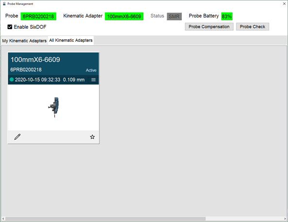
Figure 10-23 6Probe Probe Management
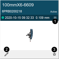
Click the Edit Probe button to add the probe tip diameter information to the current probe.
|
|
|
|
Figure 10-24 6Probe Probe |
-
Select a probe and click Edit Probe.
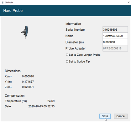
Figure 10-25 6Probe Edit a Probe
-
Notice the 6Probe serial number (last four digits) is added to the probe name.
-
Enter the name and probe tip diameter and click Save.
-
-
Select a probe to make it active.
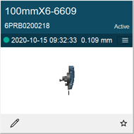
Figure 10-26 Select a Probe
-
Click the Menu button to see the last five compensations.
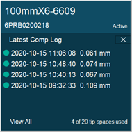
Figure 10-27 View Recent Compensations
-
Click View All button to see the complete compensation history.
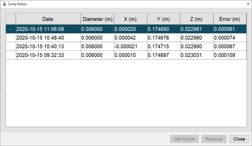
Figure 10-28 Compensation History
-
Choose a compensation and click Set Active to use it.
-
Click a compensation and click Remove to permanently delete the compensation.
-
-
Click Probe Compensation to compensate the probe. You must compensate each combination to measure accurately. Always compensate a Kinematic Adapter and Probe Tip combination after removing and reinstalling a probe tip or probe extension.
-
Click Probe Check to measure the probe and quickly check the active compensation.
-
It is not necessary to compensate a Kinematic Adapter and Probe Tip combination if removed and then later installed onto the 6Probe .
Probe Compensation
Probe compensation is a localized process by which a measurement device is optimized to perform measurements accurately. Since the probe tips are manually interchangeable, you must compensate, or measure, with the probe installed to determine the center of the ball location.
Once a probe is compensated to a 6Probe , it is not necessary to compensate it again if paired with another Vantage.
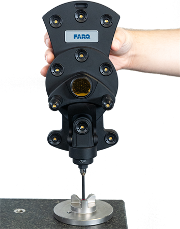
Figure 10-29 6Probe Probe Compensation
Once paired with the Vantage, the Center Status LED is blue and the Left Status LED blinks green indicating a successful pairing but an unsuccessful probe compensation.
-
Select a probe and click Probe Compensation.
Figure 10-30 Select a Probe
-
Attach the probe compensation nest to a stable work surface between 3 m (10 ft) and 5 m (25 ft) from the Vantage.
-
Click Continue.
-
-
Acquire any SMR and track it to the center of the compensation nest. Once stable, the SMR is automatically measured.
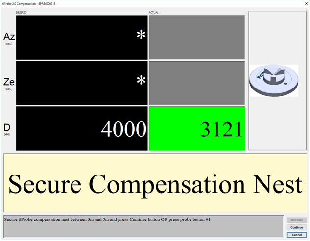
Figure 10-31 Secure the Compensation Nest
Ensure the compensation nest is secured to the measuring surface using the hole in the base or hot glue. If the nest moves at any time on the compensation process, the probe compensation may fail.
-
Track the SMR to position 1 on the base of the compensation nest. Once stable, the SMR is automatically measured.
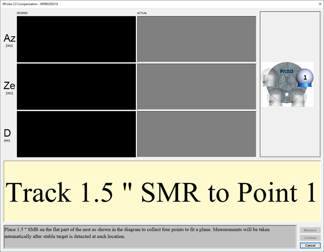
Figure 10-32 Measuring the Compensation Nest base
-
Continue for positions 2 through 4 around the base of the compensation nest.
-
-
Acquire the 6Probe and track it to the center of the compensation nest and place the probe tip into the nest. You will measure a minimum of five points in different orientations.
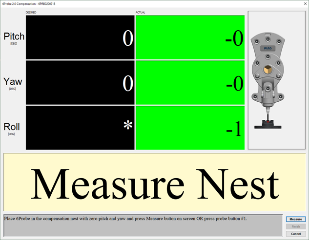
Figure 10-33 6Probe in Position 1
-
Move and twist the 6Probe until it is straight up and directly facing the Vantage. The Pitch, Yaw and Roll values should be as close to zero (0) as possible.
-
Press button 1 to measure position 1.
-
-
Continue measuring points in different orientations keeping the probe tip seated in the compensation nest. Press button 1 to measure each position.
-
Move the 6Probe 45° to each side (Roll Angle) for positions 2 and 3.
-
Move the 6Probe back to vertical center and then 15° forwards and backwards (Pitch angle) for positions 4 and 5.
-
If necessary, measure additional points in other orientations.
-
Press button 2 to continue.
The probe tip must be well-seated in the compensation nest when measuring all compensation points. Even one or two poorly measured points significantly affects the optimization process, which then has an effect on the accuracy of the 6Probe .
-
-
Compensation results:
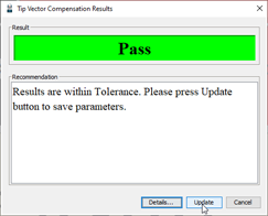
Figure 10-34 Probe Compensation Results
-
Pass - Click Update to store the probe compensation and exit. The 6Probe is now ready for use.
-
Fail - If the compensation fails, click Cancel and repeat the compensation.
-
Do Not remove the probe or power off the 6Probe until the command ends and the compensation information is written to the 6Probe .
Probe Compensation Details
Click Details to see the probe compensation details:
-
XYZ values showing the previous and the current probe location.
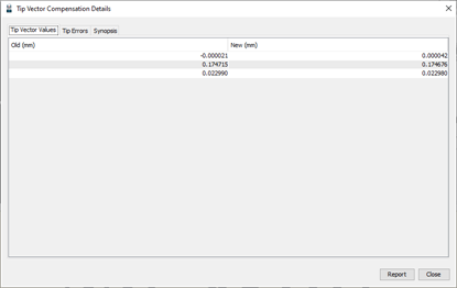
Figure 10-35 Probe XYZ Location
-
Individual compensation point results.
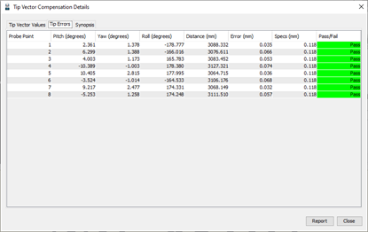
Figure 10-36 Probe Compensation Points
-
Compensation Information.
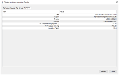
Figure 10-37 Probe Compensation Information
Probe Check
Probe Check is a method to measure the probe and compare it to the last stored compensation. This is useful when you remove and replace a probe or if you are not sure of the compensation of a probe.
Figure 10-38 6Probe Probe Check
-
Select a probe and click Probe Check.
Figure 10-39 Select a Probe
-
Place the probe tip in the compensation nest or any hole smaller than the probe tip diameter.
-
Move and twist the 6Probe and watch the green indicators in the dialog box.
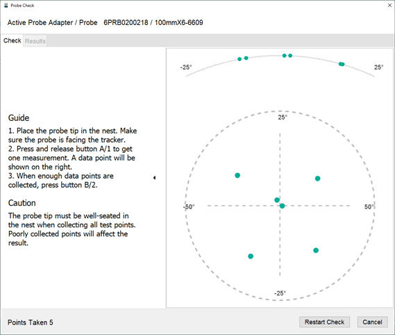
Figure 10-40 Probe Check Measurements
-
Press button 1 to measure a point.
-
-
Measure at least four different points in different orientations.
-
Press button 2 to continue.
-
-
Probe Check results are Pass or Fail. If the probe fails, compensate it again. For more information, see Probe Compensation.
-
Click the Results tab to see the details.
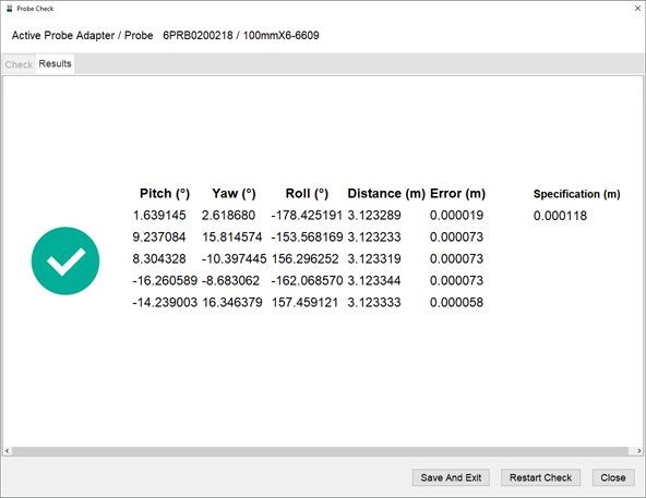
Figure 10-41 Probe Check Results
