Pointing Compensation
|
1238888 |
The Pointing Compensation, similar to the Quick Compensation, is a routine that adjusts parameters in the Vantage to improve its accuracy. The purpose of both compensations routines is to provide Angular Accuracy Results that are within your Vantage’s specifications for the full range of the system, or lower than the Vantage’s Maximum Permissible Error (MPE) based on your Vantage’s Specifications per the ISO 10360-10:2016 specification.
Compared to the Quick Compensation, the Pointing Compensation requires additional measurements and time to perform. Therefore the Quick Compensation is the preferred compensation for most applications. However, compared to the Quick Compensation, the Pointing Compensation can yield lower backsight error or improved Angular Accuracy results, especially at longer distances. Therefore, for some measurement applications, especially when measuring at long distances, Pointing Compensation can produce an improvement in overall measurement accuracy.
The Pointing Compensation consists of three parts:
-
Pointing Interim Test: A preliminary check of the Angular Accuracy or backsight error at various locations in the Vantage’s working volume.
-
Pointing Compensation: Measurements taken at specific distances from the Vantage. The purpose of these points is to improve the Angular Accuracy as the radial distance from the Vantage increases.
-
Axis Non-Squareness Compensation: Additional measurements that may further improve the Angular Accuracy. The purpose of these points is to improve the Angular Accuracy as the Vantage’s Zenith axis changes.
Equipment
The Pointing Interim Test and Compensations will require a 1½” Spherically Mounted Retroreflector (SMR) a stable nests to place the SMR in. Use either the Calibration Tripod or heavy duty nests attached to your part.
If the nests are not stable during the duration of the measurement, the Pointing Interim Test and Compensations may not be able to finish or the results can be poor.
Setup
Use this procedure with the Vantage in the normal upright position and requires an area that can accommodate the following:
-
Placing a target located at the same elevation as the Vantage at a maximum distance of 10 meters.
-
The origin of the Vantage (center of the beam steering assembly) approximately 1.25 m to 1.65 m above the floor.
Procedure
For best results, allow the Vantage thermally stabilize in the working environment.
Pointing Interim Test
-
In the CompIT dialog box, click the Advanced tab and then click Pointing Compensation. This routine requires measurement at the Home position and the following locations:
-
90 degrees azimuth, 90 degrees zenith, 6 meters distance.
-
-45 degrees azimuth, 90 degrees zenith, 2 meters distance.
-
45 degrees azimuth, 135 degrees zenith, 2 meters distance.
-
Any user defined positions.
You can loosen the mandrel mount and rotate the Vantage to adjust the Azimuth angle to the target. Make sure to tighten the mandrel mount during the Stability check.
-
-
Place the SMR in the Home position and wait until the measurement of the SMR is complete.
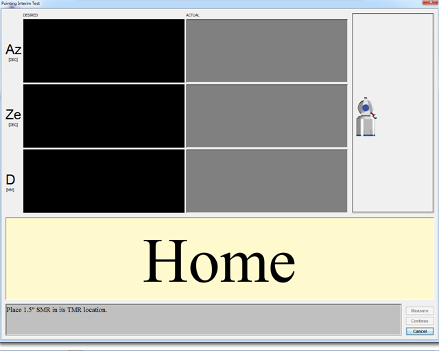
Figure 11-31 Pointing Compensation - Home
-
Track the SMR to the first location. CompIT checks for stability at the location and then automatically measures the location in both frontsight and backsight modes. The calculated difference between the two measurements is the Backsight Error.
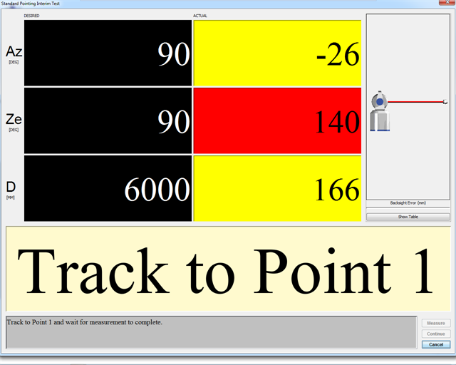
Figure 11-32 Pointing Compensation - Track to Point 1
-
DESIRED value: The target values for Azimuth, Zenith, and Radial Distance.
-
ACTUAL value: The current Azimuth, Zenith, and Radial Distance values of the SMR. The angle and distance values will be either red or yellow until you track the SMR to the desired values. The Radial distance value switches to red if the SMR is beyond its desired value. The values switch to green when the SMR is in an acceptable zone. When all of the values are green, the system waits five (5) seconds for stability before measuring the SMR.
Check the tightness of the mandrel each time by trying to manually rotate the Vantage on the instrument stand.
-
Backsight Error: The backsight error or the previously measured point. Click Show Table to show a list of the backsight errors for all of the previously measured points.
-
Cancel: Exits the Interim Test without saving any data or parameters.
-
-
Track the SMR to the second location. CompIT checks for stability at the location and then automatically measures the location.
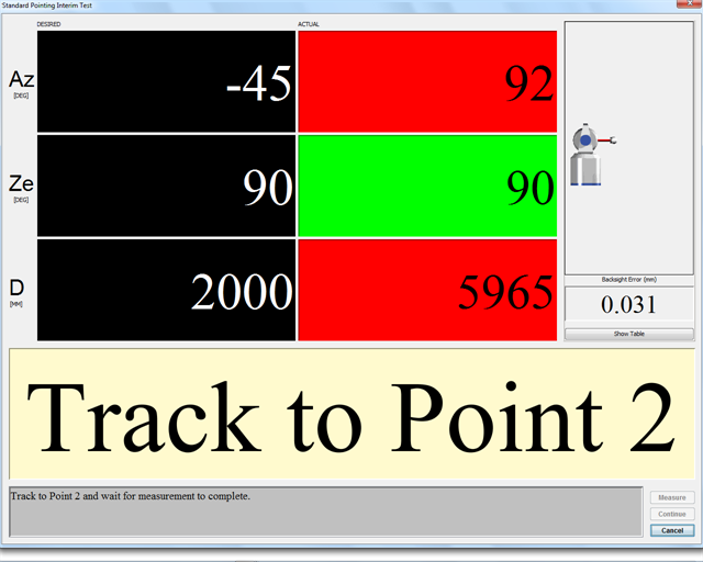
Figure 11-33 Pointing Compensation - Track to Point 2
-
Track the SMR to the third location. CompIT checks for stability at the location and then automatically measures the location.
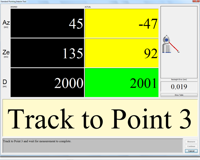
Figure 11-34 Pointing Compensation - Track to Point 3
-
Track the SMR to a user defined location. CompIT checks for stability at the location and then automatically measures the location.
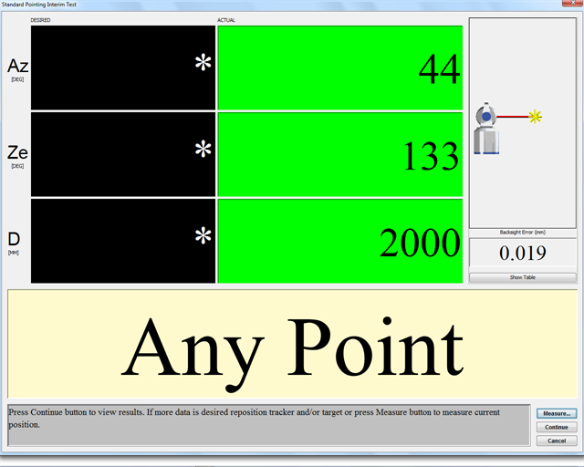
Figure 11-35 Pointing Compensation - Track to Any Point
You can continue measuring “user-defined locations.” These locations should include the full working volume or create an envelope around the object you are currently measuring. Examples include control points and points near the extreme of your part.
-
After completing the last measurement, click Continue. You will see the results of this test in the Angular Accuracy Results dialog box.
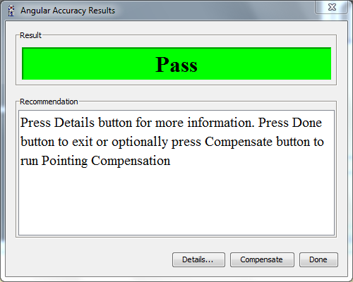
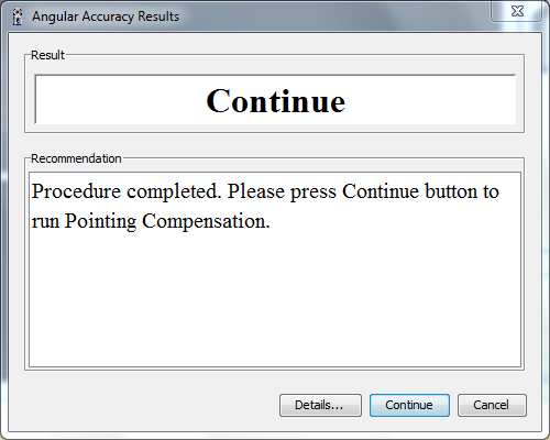
Figure 11-36 Pointing Interim Test results
-
CompIT will make a recommendation based on the results of the Interim Test:
-
If all of the points are in tolerance or below the Maximum Permissible Error, accurate measurements will be able taken with the Vantage and CompIT will report a result of PASS. Click Done to exit and return to the CompIT dialog box. You can optionally click Compensate to continue on with the Pointing Compensation to further improve the Angular Accuracy.
-
If one or more points are out of tolerance or greater than the Maximum Permissible Error, CompIT recommends continuing onto the Quick Compensation. Click Continue to start the Quick Compensation routine.
-
Click Details to view detailed results. Click Report to save the results to a text file.
-
Pointing Compensation
Clicking Compensate in the Angular Accuracy Results dialog box appears the Standard Pointing Compensation dialog box. This routine requires measurement at the Home position and the following locations:
-
any azimuth position, 90 degrees zenith, 2.0 meters distance.
-
any azimuth position, 90 degrees zenith, 3.6 meters distance.
-
any azimuth position, 90 degrees zenith, 5.2 meters distance.
-
any azimuth position, 90 degrees zenith, 6.8 meters distance.
-
any azimuth position, 90 degrees zenith, 8.4 meters distance.
-
any azimuth position, 90 degrees zenith, 10.0 meters distance.
-
Place the SMR in the Home position and wait until the measurement of the SMR is complete.
-
Place the SMR in the calibration tripod or in another stable nest and track the SMR to the first desired location. CompIT checks for stability and automatically measures the point in both frontsight and backsight modes.
-
Continue for each of the remaining desired locations.
-
After completing the last measurement, click Continue. You will see the results of this test in the Angular Accuracy Results dialog box.
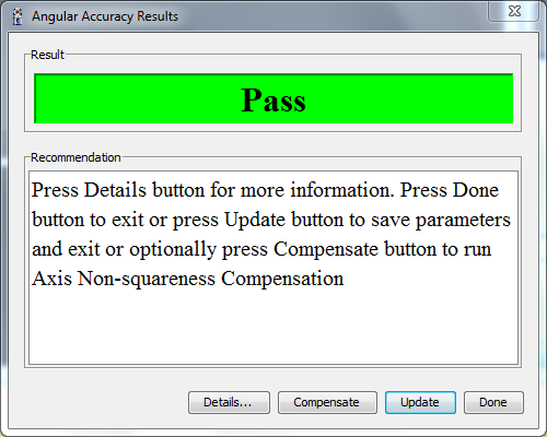
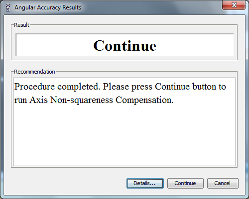
Figure 11-37 Pointing Compensation Results
CompIT will calculate new parameters generated by the Pointing Compensation, apply them to the previously measured Interim Test Points and make a recommendation based on these results:
-
If all of the points are in tolerance or below the Maximum Permissible Error, accurate measurements will be able taken with the Vantage and CompIT will report a result of PASS. Click Update to save the results and exit the routine. You can optionally press Compensate to continue on with the Axis Non-Squareness Compensation to further improve the Angular Accuracy.
-
If one or more points are out of tolerance or greater than the Maximum Permissible Error, CompIT recommends continuing onto the Axis Non-Squareness Compensation. Press Continue to start the Axis Non-Squareness Compensation routine.
-
Click Details to view detailed results. Click Report on the Details page to save the results to a text file.
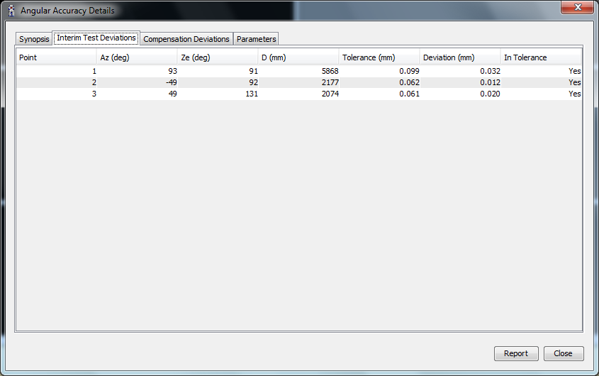
Figure 11-38 Pointing Compensation Results - Interim Test Deviations
Click the Parameters tab to view the Before, After and Change in system parameters. Pointing Compensation adjusts the two rotational (RX and RY) and two translational (CTX and CTY) parameters.
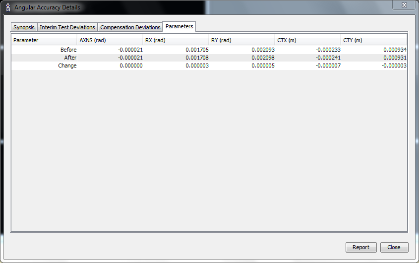
Figure 11-39 Pointing Compensation Results - Parameters
The information presented on the Parameters tab is for information only. The Angular Accuracy Checks or Backsight results is used to evaluate the accuracy of the Vantage, not these parameters.
-
Click Report to save the results to a text file.
-
Click Close to exit and return to the Angular Accuracy Results dialog box.
Axis Non-Squareness Compensation
This routine requires measurement at the Home position and the following locations:
-
0 degrees azimuth, 135 degrees zenith, 2.0 meters distance.
-
0 degrees azimuth position, 110 degrees zenith, 4.0 meters distance.
-
0 degrees azimuth position, 110 degrees zenith, 4.0 meters distance.
-
0 degrees azimuth position, 102 degrees zenith, 6.0 meters distance.
-
Place the SMR in the Home position and wait until the measurement of the SMR is complete.
-
Place the SMR in the calibration tripod or in another stable nest and track the SMR to the first desired location. CompIT checks for stability and automatically measures the point in both frontsight and backsight modes.
-
Continue for each of the remaining desired locations.
-
After completing the last measurement, click Continue. You will see the results of this test in the Angular Accuracy Results dialog box.
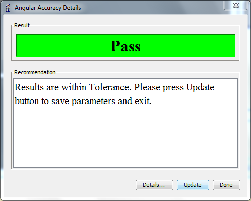
Figure 11-40 Axis Non-squareness Compensation results
-
Click UPDATE to save the results to the Vantage System.
-
Click DONE to exit the Axis Non-squareness routine without saving the results.
-
Click DETAILS to see the results.
