Accuracy Specification and Formulas
|
1238888 |
The following discussion presents details on the accuracy for the Vantage per the ISO 10360-10:2016 specification. Accuracy is expressed as Maximum Permissible Error (MPE). Typical performance is half the MPE values.
See Table 9-1 for the performance specifications for the Vantage.
|
Laser Tracker Subsystem |
Symbol |
Maximum Permissible Error |
|
|
Absolute Distance Meter (ADM) |
|
|
(1) |
|
R0 parameter (R0) |
|
|
(2) |
|
Transverse |
|
|
(3) |


The geometrical arrangement of a Laser Tracker that measures the coordinates of points 1 and 2 is shown in Figure 9-1. From these coordinates, the length d is determined. The maximum permissible error (MPE) in this length measurement is the maximum error permitted by the performance verification tests. The MPE of measured length d,  , is calculated using Equation (6) below.
|
|
|
|
|
|
|
|
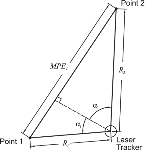

The angles  and
and  are positive in the directions shown in Figure 9-1 and negative in the opposite directions. The quantities
  ,
,  ,
,  ,
,  , and
, and  are calculated using Equations (1) - (3). The subscript 1 refers to path 1 and the subscript 2 refers to path 2. So, for example,
  .
.
A special case is the outside buck-in measurement in which the Laser Tracker is aligned with points 1 and 2 as shown in Figure 9-2.
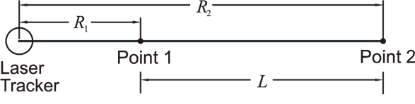
Figure 9-2 Laser Tracker Buck-In geometry
Point 1 establishes the reference for the measurement, much as the home position establishes the reference point for many other measurements. Also, in this case, the air temperature of the beam path between the Laser Tracker and point 1 is the same for both measurements. Under these conditions, the two coordinate measurements are correlated, permitting Equation (6) to be rewritten as:

Another special case is that of the two-face measurement. In this measurement, the coordinates of a point are first measured in the usual mode, referred to as front-sight mode, and then in the backsight mode. To put the Laser Tracker in backsight mode, the azimuth axis is rotated by 180 degrees and then flipped about the zenith axis to point the laser beam back at the target. The transverse distance between the frontsight and backsight coordinates is the backsight error. The two-face test is a challenging test of performance because most of the Laser Tracker transverse errors are doubled. The two-face MPE is:
 (7)
(7)
Probing Error
This section presents details on the probing accuracy for the Vantage per the ISO 10360-10:2016 specification. The calibration artifact is a 51 mm diameter sphere located at a range of 2 meters.
|
Probing Measurement |
Symbol |
Maximum Permissible Error |
|
Size |
Psize |
20 μm |
|
R0 parameter (R0) |
Pform |
30 μm |
|
Table 9-2 ISO 10360-10: 2016 Probing Errors |
||
The ISO 10360-10: 2016 probing errors are satisfied for measurements acquired with SMRs conforming to the specifications of less than ¼ wave wavefront distortion and a maximum algebraic dihedral angle difference of less than 1 arcsecond.
Maximum Permissible Error
Vantage calibration begins with the required test length positions and MPEs. All scale bars used are 2.30 meters long.
|
Formula for MPEs 1-35 & 41: Figure 9-1, Table 9-1, and Equation (6) of this manual. |
|
Formula for Ranging MPEs (positions 36-40): Figure 9-2, and Equation (7) of this manual. |
|
Test Length Position |
MPE (μm) |
Test Length Position |
MPE (μm) |
|
|
1 |
39 |
|
22 |
41 |
|
2 |
39 |
|
23 |
49 |
|
3 |
48 |
|
24 |
49 |
|
4 |
48 |
|
25 |
49 |
|
5 |
48 |
|
26 |
49 |
|
6 |
48 |
|
27 |
49 |
|
7 |
48 |
|
28 |
49 |
|
8 |
48 |
|
29 |
49 |
|
9 |
48 |
|
30 |
49 |
|
10 |
48 |
|
31 |
71 |
|
11 |
70 |
|
32 |
71 |
|
12 |
70 |
|
33 |
71 |
|
13 |
70 |
|
34 |
71 |
|
14 |
70 |
|
35 |
71 |
|
15 |
70 |
|
36 |
71 |
|
16 |
70 |
|
37 |
71 |
|
17 |
70 |
|
38 |
71 |
|
18 |
70 |
|
39 |
71 |
|
19 |
70 |
|
40 |
49 |
|
20 |
41 |
|
41 |
49 |
|
21 |
41 |
|
|
|
|
ISO 10360-10:2016 ranging test positions 36-40 satisfied to 75 meters. |
||||
