Probes
|
1238888 |
The Probes group controls your
Probe Management
Click Probe Management to change and edit a probe. In the Probe Management dialog box you can:
-
Select the current probe and view the Compensation Status.
-
Create, Edit or Delete, or Duplicate a probe.
-
Compensate the current probe.
-
View the compensation log for the current probe.
-
Start the Single Point Articulation Test (SPAT).
-
Run an Arm Compensation or reset to the FARO Factory Arm Compensation.
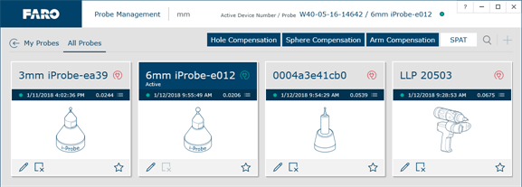
Figure 10-14 Probe Management
The Compensation Status and compensation date display for every probe.
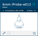
Figure 10-15 Probe Information
If you do not see all of the probes, click Find to search the
Compensate each of these probes before you begin measuring your parts. See Probe Compensation Overview and Probe Compensation
Probe Compensation List
Click the list to show the most recent compensations.
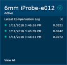
Figure 10-16 Probe Compensation List
-
Click View All to see the Compensation Log. See View Log.
Single Point Articulation Test (SPAT)
Click SPAT to run a Single Point Articulation Test (SPAT) with your
Arm Compensation
Click Arm Compensation to create a user arm compensation for your
Click Add to add a new probe. See Edit Probe.
You can also select any probe and click Duplicate to create another probe.
Using FARO iProbes
The standard 3 mm and 6 mm probes are FARO iProbes. The exact diameter is electronically recorded on the iProbe. You do not need to edit any parameters of the standard
This generation of FARO iProbe will not attach to the
Edit Probe
Select any probe and click Edit to modify the details of the current probe.
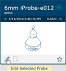
Figure 10-17 Editing a Probe
Modify any settings and click Save to continue.
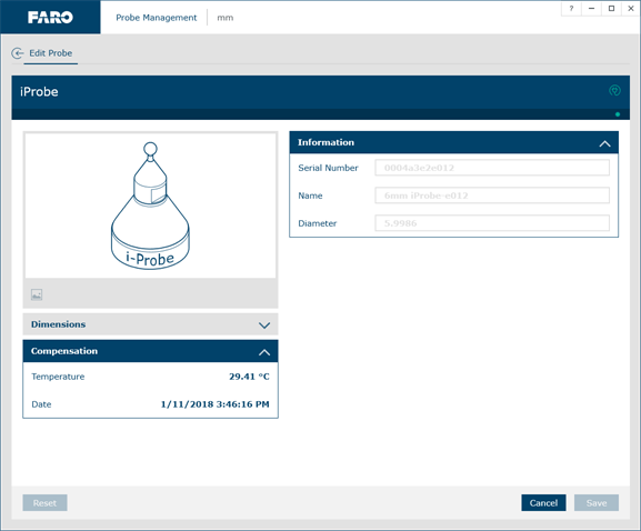
Figure 10-18 Modify Probe dialog box
The new probe is now current. You must compensate the new probe.
Probe Compensation Overview
Probe compensation is a localized process by which a measurement device is optimized to perform measurements accurately.
To understand probe compensation, you must first understand the
Measurement accuracy relies on probe compensation under optimal conditions. If the probe compensation passes, measurements will be accurate. If the probe compensation fails, measurements will not be as accurate. Proper mounting and technique are critical compensation factors.
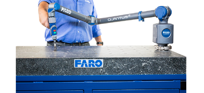
Figure 10-19 Probe Compensation
To optimize compensation and minimize stress-induced errors during this critical procedure, place the
Using the Quantum Max Extension Adapter
If you are using the
You measuring software may not support this feature of the FaroArm Driver.
-
After the last compensation point, simply record an additional point with the probe straight and upright in the cone or hole. If you are using the Sphere method, then the probe must be straight and upright to your measuring surface.
