Diagnosing FARO Laser Line Probe Accuracy Problems
|
1238888 |
Always correct
q Clean the top and bottom lenses with the cloth from the Laser Line Probe case. Dirt and grease on either lens can cause poor results.
q Place the FARO Compensation Plate within approximately ⅔ of the
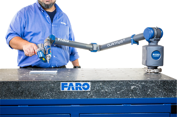
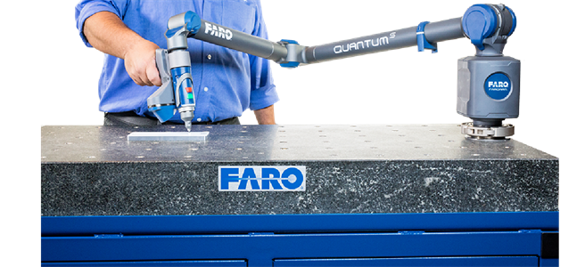
Figure 7-9 Laser Line Probe Compensation
Secure the plate firmly to the table. If you are clamping at more than one location, make sure that the surface is flat so that the plate does not bend. Clamping only on one end may create a “spring board” effect.
FARO Laser Line Probe Compensation
q Ensure the Scan Rate and Scan Density are set 1/1. In the Probe Management dialog box, edit the current Laser Line Probe. to access the FARO Laser Line Probe Control dialog box.
q Perform the compensation at least 3 times. For more information, see FARO Laser Line Probe Compensation.
You will take 75 scans in the five positions during the compensation process.
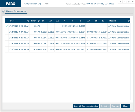
q In the probe compensation log, check the X, Y, Z values. Each value should repeat to within:
X: 100 µm (0.0039 in)
Y: 50 µm (0.0019 in)
Z: 50 µm (0.0019 in)
If additional support is required, contact your Customer Service Representative by Phone, Fax or Technical Support.
When contacting FARO ’s Customer Service, please provide the following information:
-
The serial number of the device(s).
-
A copy of the probe compensation log.
-
A copy of the event log.
-
A copy of the Single Point Articulating Test (SPAT).
-
Pictures of the setup.
