Registration View
|
123-2026-04-28-888 |
Click the registration view icon .
The registration view is opened. This is the main view of the interactive registration.
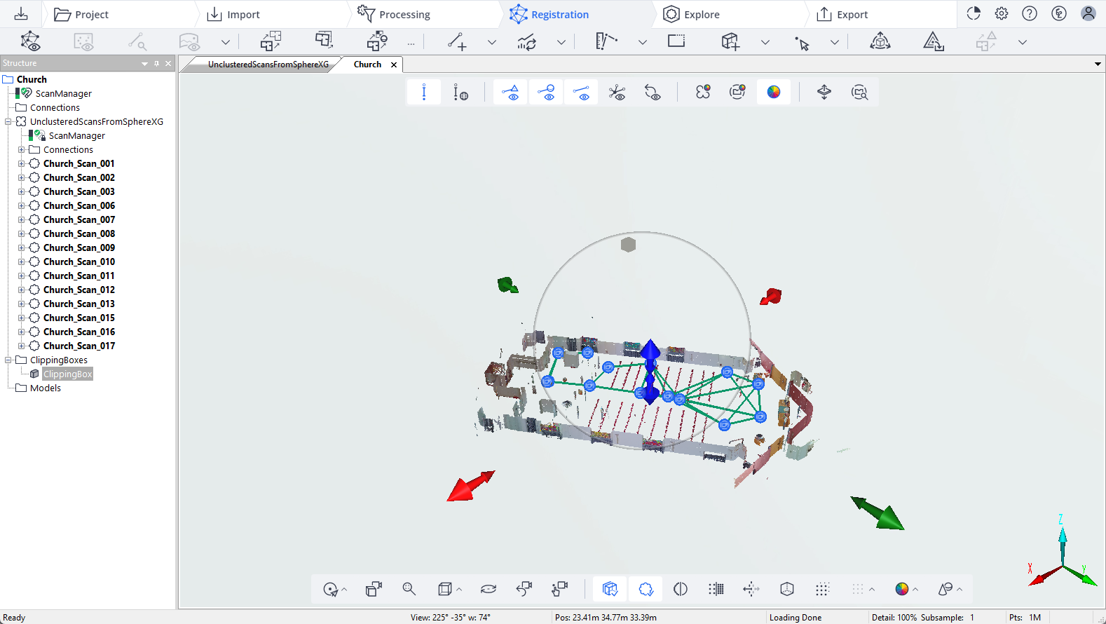
Figure 9-3 Interactive registration view with hidden clipping box
If you do not select an object in the structure view, there are two options:
-
There is only one cluster under the root element. In this case, the registration view of the cluster is opened.
-
There is more than one cluster under the root element. In this case, the registration view of the root element is opened.
To show the registration view of a particular cluster, click the cluster you want in the structure view.
The registration view displays the registration results in an intuitive, visual way. Connections between scans, targets and reference points are colorized based on the registration results (see below). With the interactive registration tools and the registration toolbar you can interact with the registration:
-
Add, delete, edit and compute connections
-
Search correspondences
-
Quickly optimize scan positions
-
Update the registration statistics, etc.
For further information on the interactive registration tools, see Interactive Registration Toolbars and Tools.
Scan Symbols
The following symbols may be displayed in the registration view:
 Blink scan
 Focus scan
 Focus Flash scan
 Focus PanoCam scan
 Orbis scan
 Orbis Flash scan
 POI image
 Standard image
Connections
Connections are only displayed, if a pre-alignment in Stream or a previous registration in SCENE was done. However, you can add new connections and refine them, either as an individual step by selecting Refine New Connections from the Add Connection dropdown list or by clicking Update Registration.
The interactive registration shows connections between scans, between scans and targets and between scans and reference points.
Connections may have different colors depending on their state:
-
Blue: New connections that have not yet been refined are displayed in blue.
-
Green: Connections are green if the scan point error is below the green value specified in the registration settings.
-
Yellow: Connections are yellow if the scan point error is between the green and the red value specified in the registration settings.
-
Red: Connections are red if the scan point error is above the red value specified in the registration settings.
-
Purple: Connections are purple if they were rejected by the scan position optimization due to a big scan point error.
This color coding applies to connections between scans, between scans and targets and between scans and reference points.
 Connections between targets are solid.
 Connections between scans and targets are thin dash lines.
 Connections between scans and reference points are thick dash lines.
See examples in the figure below:
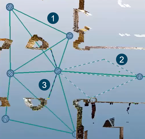
Figure 9-4 Interactive registration connections
If connections overlap, do a right-click and select the connection you want. The connection is then highlighted in the registration view and in the structure view.