3D and Registration Views Settings
|
1238888 |
The settings for the 3D view and the registration vieware separated into Display and Navigation settings. All these settings will be applied when a new 3D view or the interactive registration views are opened. These settings will not be applied to views which are already opened.
Scan Point Cloud Generation
If scan point clouds do not exist and you open any 3D view a scan or a cluster, the corresponding scan point clouds will be created automatically. This is the default behavior. Note that this is only possible for processed scans, not for raw scans.
To deactivate this option, unmark checkbox If scan point clouds do not exist for scans in the opened view automatically create them.
This is especially useful for full downloads from Sphere XG, because scan point clouds are not downloaded. However, you should deactivate this option for light Sphere XG downloads.
Navigation
Default Mode: Select the navigation mode to be activated when you open a new 3D view. You can select among Fly, Examine, or Smart mode as default navigation modes. Depending on your selection, the 3D toolbar button changes its appearance.
Invert Mouse Wheel: Changes the forward and backward movement by the mouse wheel. The default behavior of the mouse wheel is: spinning it forward will move the view backwards in space and vice versa.
Use Positional Zoom (instead of Optical Zoom): Sets the zoom mode for the 3D view. The default zoom is a positional zoom, meaning that it zooms by behaving as if the position of the camera (that is, the position from which you observe the scan) is moving toward the position of the cursor on the screen. This allows you to do things like zoom past or through objects. Prior to SCENE 2019.1, the default zoom was an optical zoom, meaning that it zoomed by increasing the magnification of the scan (as if you were standing in one position and using a zoom lens to magnify the scan). Note that you can toggle between these two modes on-the-fly by pressing and holding the SHIFT key
Default Movement Speed: Change the speed of the left, right, forward and backward movement triggered by pressing the cursor keys.
Acceleration Factor: This is the factor which is used to determine the accelerated speed. The accelerated speed is the factor multiplied with the default speed. The accelerated speed is used by pressing the cursor keys in combination with the SHIFT key.
The settings Invert Mouse Wheel, Default speed and Accelerated Factor will be applied to the opened view.
Display – Effects
Supersampling: renders the point cloud with a resolution higher than the resolution of your screen and then shrinks the point cloud to fit the screen resolution. This reduces anti-aliasing effects and gives the point cloud a smoother visual appearance. Fine and filigree structures look sharper and stray points will appear less annoying. Set the resolution of the initially rendered point cloud compared to the screen resolution by selecting one of the options 2x2, 3x3, or 4x4. For example, choosing 2x2 means that the point cloud will be rendered with a resolution that is 4 times the resolution of your screen.
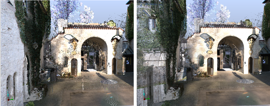
Figure 5-10 Supersampling turned off (left) and turned on (right)
Objects like walls might appear transparent when using small point sizes in combination with supersampling.
High supersampling resolutions such as 4x4 require large amounts of graphics card memory.
Gap Filling: The gap filler fills gaps between scan points that are physically close to each other.
Clear View: In the clear view mode, points in areas with low point density will be displayed more transparently and points in areas with a high point density will be displayed more brightly. It adds transparency to the otherwise completely opaque point cloud rendering. This allows for viewing through walls or ceilings and may give a much better impression of the spatial structure of the underlying point cloud. Points in areas with low point density will be displayed more transparently and points in areas with a high point density will be displayed more brightly.
Changing the effects will be applied if a new 3D view is opened. The effects which can be changed directly in the 3D view are only applied to the 3D view which is opened.
Gap filler or clear view can only be activated if supported by hardware.
Display – Background
Select either Environment Map or Color Gradient.
Environment Map
See Environment Map as Background Image for a 3D View
Color Gradient
The gradient background color starts with the selected top color and transitions linearly to the selected bottom color.
- Click the Top Color button to open the color selector dialog.
- Select the color that you want the background to start at the top of the display.
- Click the Bottom Color button to open the color selector dialog.
- Select the color that you want the background to start at the bottom of the display.
Display – Scans
Loaded scan replaces scan point cloud in 3D view
Two representations of a scan exist in your project, the original scan points and the optimized scan point cloud. If this option is selected and the scan is loaded, the original scan points are used for visualization instead of the scan point cloud.
The scan point cloud representation is optimized for visualization performance of a scan. Any combination of original scan points and scan point clouds in a single view will disable tools such selections and the visualization performance may degrade. Deactivate this setting to avoid these issues.