ADM Checks
|
1238888 |
The ADM Interim Test compares the distance between two points measured from a position that uses a large amount angular rotation to the distance between the same two points measured from a position that uses almost all radial measurements or a very small amount of angular rotation. These two measurement orientations have different sources of error and can therefore be used as a field check for the Vantage’s ADM System.
FARO recommends to perform this test immediately after performing a Pointing Compensation.
The ADM Interim Test will require a 1½” Spherically Mounted Retroreflector (SMR) and two stable nests to place the SMR in. The Calibration Tripod used for the Angular Accuracy Checks and Pointing Compensations cannot be used for this test. Two points glued to the floor can be used but two points on heavy duty instrument stands can provide better alignment percentages.
Alternatively, you can perform this test with a bar with two fixed targets where the bar moves to different locations and the Vantage remains in the same location. If you use a bar with two fixed targets, securely mount the bar during the measurements to prevent any changes in its length from bending or flexing.
For best results, FARO recommends to run this test immediately after performing a Pointing Compensationfrom the Advanced tab.
-
In the CompIT dialog box, click the Advanced tab and then click ADM Checks.
The first position for the interim test is with the Vantage set up to measure two points from the side. This setup should maximize the use of the Vantage’s angular encoders. FARO recommends to set up the Vantage three (3) meters away from two points that are one (1) or more meters apart. After measuring the second point, the software reports the percentage of the measurement that is made with the encoders. FARO recommends a percentage of 80% or higher to obtain a meaningful result in this test. To obtain a percentage of 80% from this position, place the points at the following locations:
-
Point 1: 110 degrees Azimuth, 90 degrees Zenith, 3000 mm Radial Distance
-
Point 2: 80 degrees Azimuth, 90 degrees Zenith, 3000 mm Radial Distance
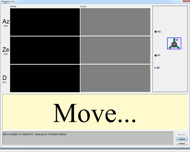
Figure 11-41 Move to Station S1
-
-
Move the Vantage to Station S1 and click Continue.
-
Move the SMR to the Home position. An acaption-figureuto-adjust completes at the Home position to normalize the ADM for the test.
-
Track or send the beam to Point 1. To send the beam, click Motors Off and manually steer the beam to the target.
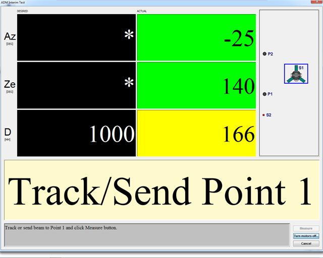
Figure 11-42 Beam tcaption-figureo Point 1
-
Measure Point 1 by clicking Measure. A check is made to ensure the target is stable and then the measurement is taken.
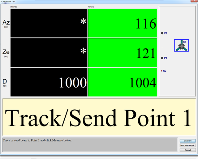
Figure 11-43 Measure Point 1
-
Track, or send, the beam to Point 2. A pie chart indicates the percentage of the measurement that is made with the angular encoders. FARO recommends to achieve a percentage of greater than 80%. If the target position yields a number lower than 80%, a message box appears and tells you where to move the SMR.

Beam to Point 2
-
Click Measure to measure Point 2.
-
If the pie chart shows a percentage greater than 80%, the setup for the first measurement is good. Click Continue to proceed. If the percentage is less than 80% FARO recommends that you re-measure. Click Retry to re-measure the two points with a setup that yields greater than 80%.
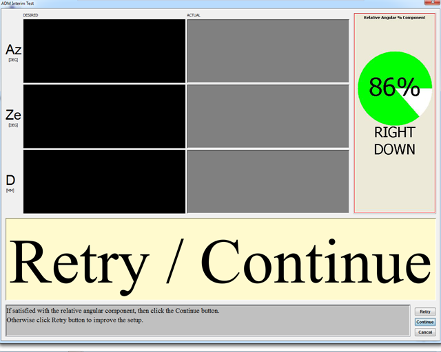
Figure 11-44 Retry/Continue 2
Position #2
-
Move the Vantage to Position 2. Position 2 should orient the Vantage in such a way as to maximize the distance measurement component of the measurement; that is, the laser beam should be in line with the two measurement points. Use a range of 1 to 2 meters from point one; however, you can use any distance.
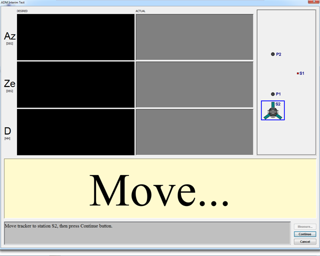
Figure 11-45 Move to Position 2
-
Click Measure to measure Point 1. A check is made to ensure the target is stable before the measurement is taken.
-
Track or send the beam to Point 2. A pie chart indicates the percentage of the measurement that is made with ADM. FARO recommends to use a percentage of greater than 80%. If the target position yields a number lower than 80%, a message box appears and tells you where to move the Vantage (or bar if a bar with two targets is used).
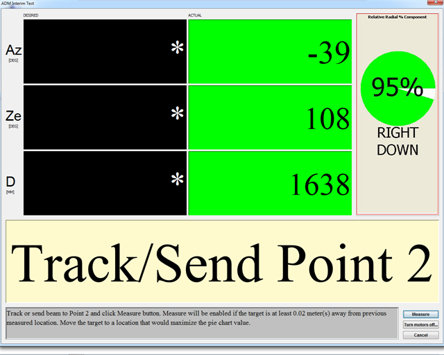
Figure 11-46 Beam to Point 2
-
Click Measure to measure Point 2.
-
If the pie chart shows a percentage greater than 80%, then the setup for the second position is good. Click Continue to proceed. If the percentage is less than 80% FARO recommends that you move the Vantage and re-measure. Click Retry to re-measure the two points with a setup that yields greater than 80%.
-
The ADM IT results dialog indicates the distances measured between the two points from the two setups and the percentage of angular and distance measurements. A result from setups with greater than 80% indicates a valid test. The difference between the two measurements is shown along with the Maximum Permissible Error (MPE), which is derived from the system’s angular specifications. A result (Pass/Fail) appears.
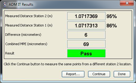
Figure 11-47 ADM IT Checks dialog box
-
Click Report to open a dialog to save the results to a comma delimited text file. A check box is available to append the report to a previous report. Appending the report creates a log file of the test results. Click Done to close the results page.
-
The Measure More Points button returns to the Move screen and prompts for another set of two points from another Vantage (or bar) position. This allows for additional distances to be measured in the testing of the ADM. For example, measure from two (2), four (4), and six (6) meters.
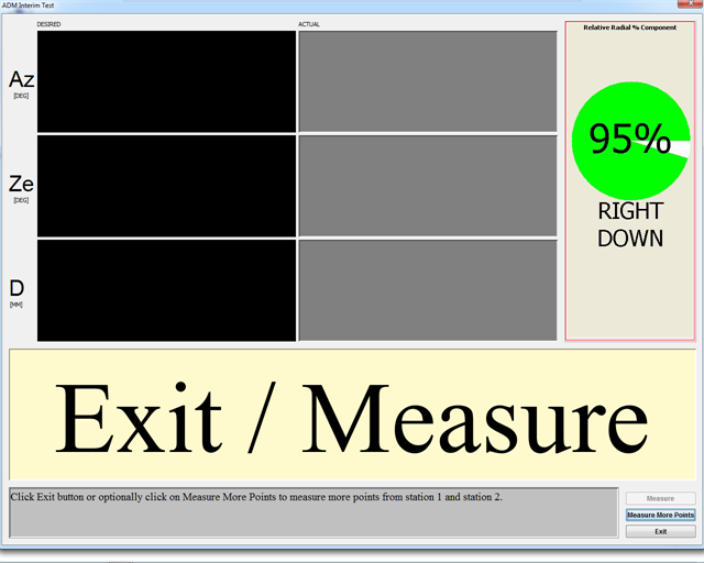
Figure 11-48 Measure More Points
-
Click Exit to end the test.
