Angular Accuracy Checks
|
1238888 |
Run this check after Startup Checks, before each measurement session, or if the temperature has changed more than approximately 2.8° Celsius (5° Fahrenheit). The Angular Accuracy Check verifies the system's accuracy during the course of a measurement session with minimal disruption. The CompIT Angular Accuracy Check measures the SMR in both frontsight and backsight, and calculates the difference between the angular component of these two measurements, or the Backsight Error. The Angular Accuracy Check can collect backsight deviations anywhere in the measurement volume.
The Angular Accuracy checks compares the measured error to the Vantage’s Maximum Permissible Error (MPE) based on your Vantage’s specifications per the ISO 10360-10:2016 specification. If the measured error is greater than the MPE, CompIT recommends a Quick Compensation.
The Angular Accuracy Checks require a 1½” Spherically Mounted Retroreflector (SMR) and stable nests to place hold the SMR. You can use either the Calibration Tripod or heavy duty nests attached to your part. If the nests are not stable during the duration of the measurement, the Angular Accuracy test may not be able to finish or its results can be poor.
-
In the CompIT dialog box, click Angular Accuracy Checks. The Select Mode dialog box appears with two options:
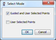
Figure 11-5 Select Mode dialog box
-
Guided and User Selected Points first measures the Angular Accuracy at three specific locations recommended by CompIT with the option to measure additional locations after.
-
User Selected Points measures the Angular Accuracy at any location you choose. When using this option, you must use a minimum of three locations. The points should be at multiple distances and should cover the measurement volume of your part or tool.
-
-
After selecting a mode, the measurement screen appears:
-
Place the SMR in the Tracker Mounted Reset (TMR) or Home position. Allow the Vantage to measure the TMR position.
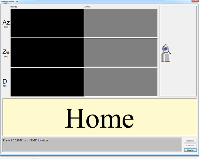
Figure 11-6 Guided and User Selected Points - Home
-
-
After the Vantage automatically measures the Home position, track the SMR on the tripod to the desired location.
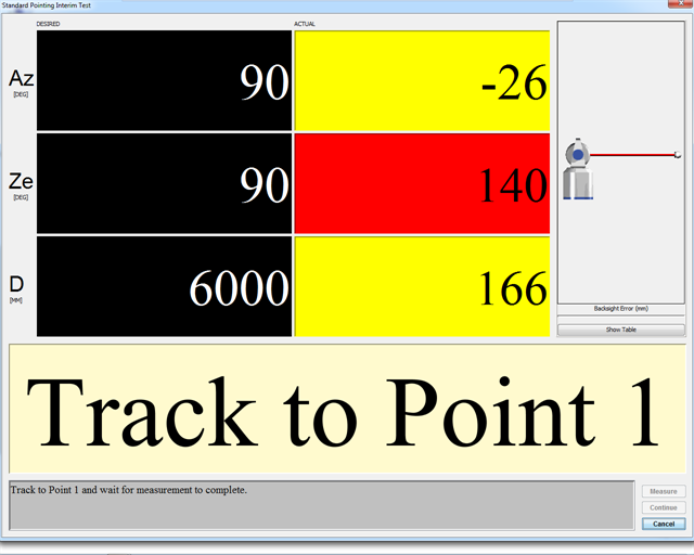
Figure 11-7 Guided and User Selected Points - Track to Point 1
-
DESIRED value: When measuring Guided Points, these are the target values for Azimuth, Zenith and the Radial Distance. When measuring User Selected Points, the value is an *.
-
ACTUAL value: The current Azimuth, Zenith, and Radial Distance values of the SMR. When all of the values are green, the system waits five (5) seconds for stability before measuring the SMR. When measuring User Selected Points, the values will always be green. When measuring Guided Points, the values switch to green when the SMR is in an acceptable zone around the desired values. The Radial distance value switches to red if the SMR is beyond its desired value.
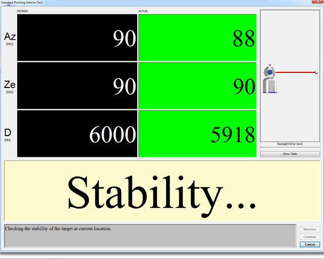
Figure 11-8 Stability
If the SMR does not stabilize within 60 seconds, an error message appears. Check the stability of the SMR and the Vantage before trying again.
If the Vantage and SMR are mounted properly and the measurement still does not stabilize or takes longer than normal, please check for airflow or other environmental issues.
When the measurement is complete, the backsight error shows on the left side of the screen. After taking multiple measurements, click Show Table to show a list of any previous backsight errors.
You can change the stability delay by clicking Customize in the Advanced tab of the CompIT dialog box. See General. You can disable the Auto Measure function by clicking Settings in the Advanced tab of the CompIT dialog box. See Settings. When Auto Measure is disabled, take measurements by clicking Measure.
-
-
When the backsight measurements at the first location are complete, move the SMR to the second location. Track the SMR to the next location and wait for stability.
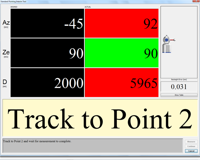
Figure 11-9 Guided and User Selected Points - Track to Point 2
-
After completing the last backsight measurement, click Continue. You will see the results of this check in the Angular Accuracy Results dialog box.
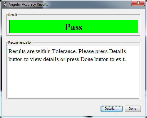
Figure 11-10 Angular Accuracy Results dialog box
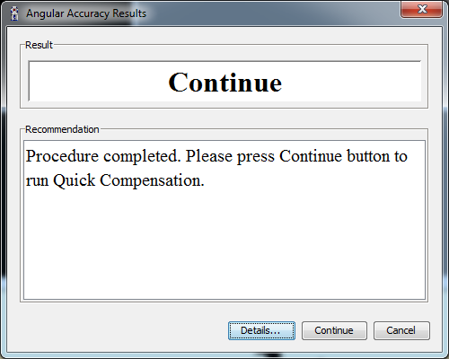
Figure 11-11 Angular Accuracy Check complete
CompIT compares the measured Angular Accuracy to the Vantage’s Maximum Permissible Error (MPE) based on your Vantage’s specifications per the ISO 10360-10:2016 specification. The Results Dialog box will report PASS if the results are in tolerance and will report Continue with a recommendation to run the Quick Compensation Routine if they are out of tolerance.
-
Click Done, or Continue to follow CompIT's recommendation, or click Details to see the detailed results.
Click the Angular Accuracy Check Deviations tab to view the detailed results of the backsight measurements. The measurement location, the error, the tolerance (MPE) and if the measurement is In Tolerance or Out of Tolerance appears.
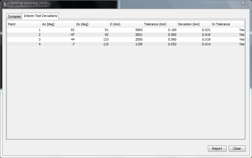
Figure 11-12 Angular Accuracy Check Deviations tab
-
Click Close to continue.
-
The Angular Accuracy Checks automatically close.
