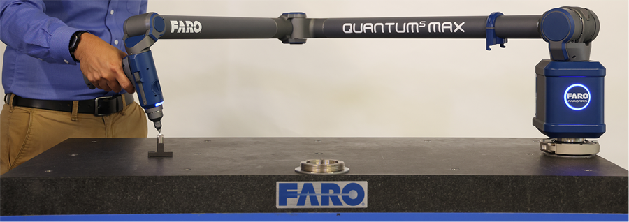
Quantum Max Setup
|
1238888 |
q Check that ambient temperature is not fluctuating more than 3°C (5.4°F) over a five minute period.
-
InCAM2 2024 or CAM2 Measure, run the Devices > Device Center command and click Temperature.
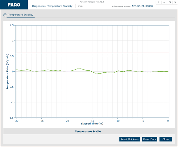
Figure 7-4 Temperature Stability dialog box
Probe Setup
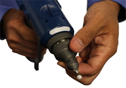
Figure 7-5 Installing a Probe
q Check probe seating.
q Install by hand.
q Verify that the probe has no chips or cracks, is not loose, and that it has no flat spots.
Probe Compensation
q Place the compensation cone approximately ⅔ of the
q Perform the probe compensation at least 3 times. For more information, see Hole Compensation Method.
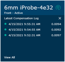
q Look in the probe compensation log and compare the X, Y and Z values. Each value should repeat to within the
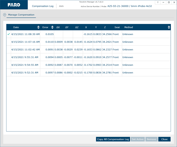
Figure 7-7 Probe Compensation Log
If one person is able to repeat better than another person, review probe compensation procedure. A “green light” does not guarantee a good probe compensation. It simply indicates that the data collected was within specification.
Mounting
Most accuracy and repeatability problems can be attributed to improper mounting of the
q If using a magnetic mount, check that mating surfaces are clean and free of debris.
Small metal shavings can cause the magnetic mount to rock back and forth. The magnet will naturally attract these shavings.
q If using a vacuum mount, check that mating surfaces are clean and free of debris. Ensure you are using the proper amount of vacuum oil.
Base Deflection
-
Click Diagnostics > Base Deflection.
-
Set up the FARO compensation cone approximately ⅔ of the
You can also use a 5 mm (0.2 in) machine drilled hole on your part. The hole does not have to be exactly 5 mm (0.2 in), but it must be smaller than the probe’s diameter and have a smooth seat.
-
Place a properly compensated probe firmly in the cone or hole.
-
Click Reset Data to begin the test.
-
Press the green Front button and apply up to 3 pounds-force (13 Newtons) to the base of the
Press the green Front button to reset the screen at any time.
-
Press the red Back button to stop.
-
Any deflection of the base is recorded and displayed on the screen. All of the points must be within the circle on the graph.
-
Rotate the mouse wheel to zoom in and out of the chart. Right-click and drag to move the chart around the window.
-
Click Reset Plot Axes or double-click the wheel button to reset the chart view.
-
-
Click Close to exit.
Tilt
-
Click Diagnostics > Diagnostic Tilt.
-
Hold the handle in the air approximately ⅔ of the
-
Press the green Front button and move the tubes and joints of the
-
Any tilt of the base is recorded and displayed on the screen. All of the points must be within the circle on the graph.
-
Press Reset to clear the screen.
If the Base Deflection test fails and the Tilt test passes, check the stability of your part.
