Navigation Toolbar (3D View only)
|
1238888 |
A navigation toolbar is displayed only with the 3D view.

Figure 4-4 3D Navigation toolbar
The following options are available in the 3D navigation toolbar:

|
Note that the appearance of this button depends on your Views default settings. |

|
|

|
|

|
|

|
|

|
|

|
|

|
|

|
|

|
|

|
|

|
Backface Culling |

|
|

|
|

|
|

|
|

|
View Modes
Examine Mode 
Click Examine Mode to start the object-based navigation. The objects will appear to move while you stand still.
Smart Mode
The Smart Mode combines different navigation modes.
A ring is used to divide the view into different zones. When starting the actual navigation by clicking the mouse button, different navigation modes will be used depending on the zone.
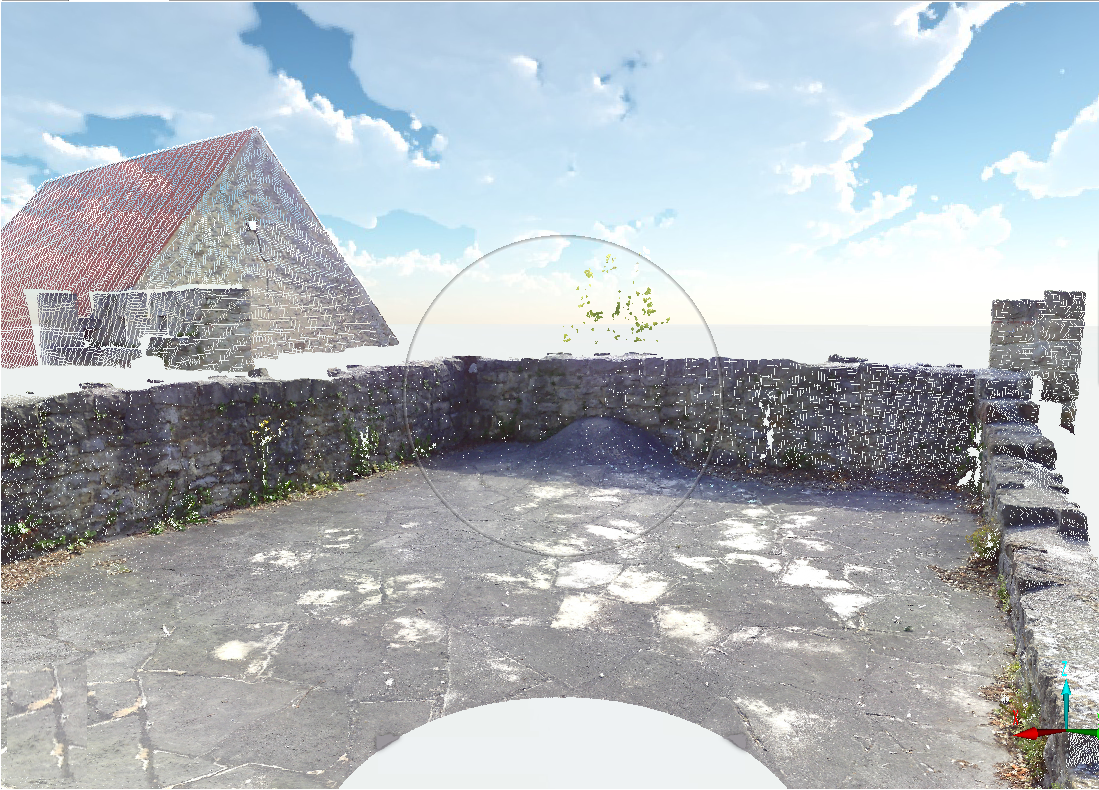
Figure 4-5 SCENE with activated Smart Mode
The navigation ring disappears when the mouse is not moved anymore, or while you are clicking and moving the view. It appears again as soon as you hover with the mouse.
2 Zone navigation (default)
A thin ring visualizes the two zones. The cursor updated depending on its position.
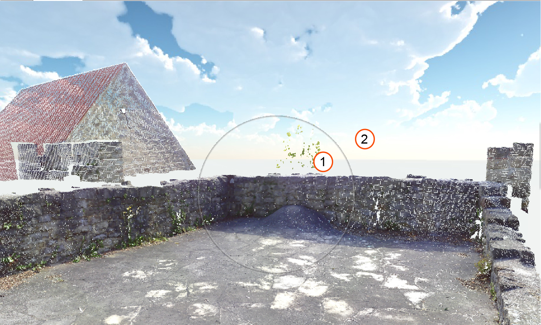
Figure 4-6 2 Zone navigation
-
Fly Mode: activated if the cursor is in the inner of the ring.
-
Examine mode: Activated if the cursor is in the outer area of the ring.
3 Zone navigation
A thick ring visualizes the three zones. The cursor is updated depending on its position.
To set the 3 Zone navigation, you must switch to the SCENE classic style user interface by clicking Settings >
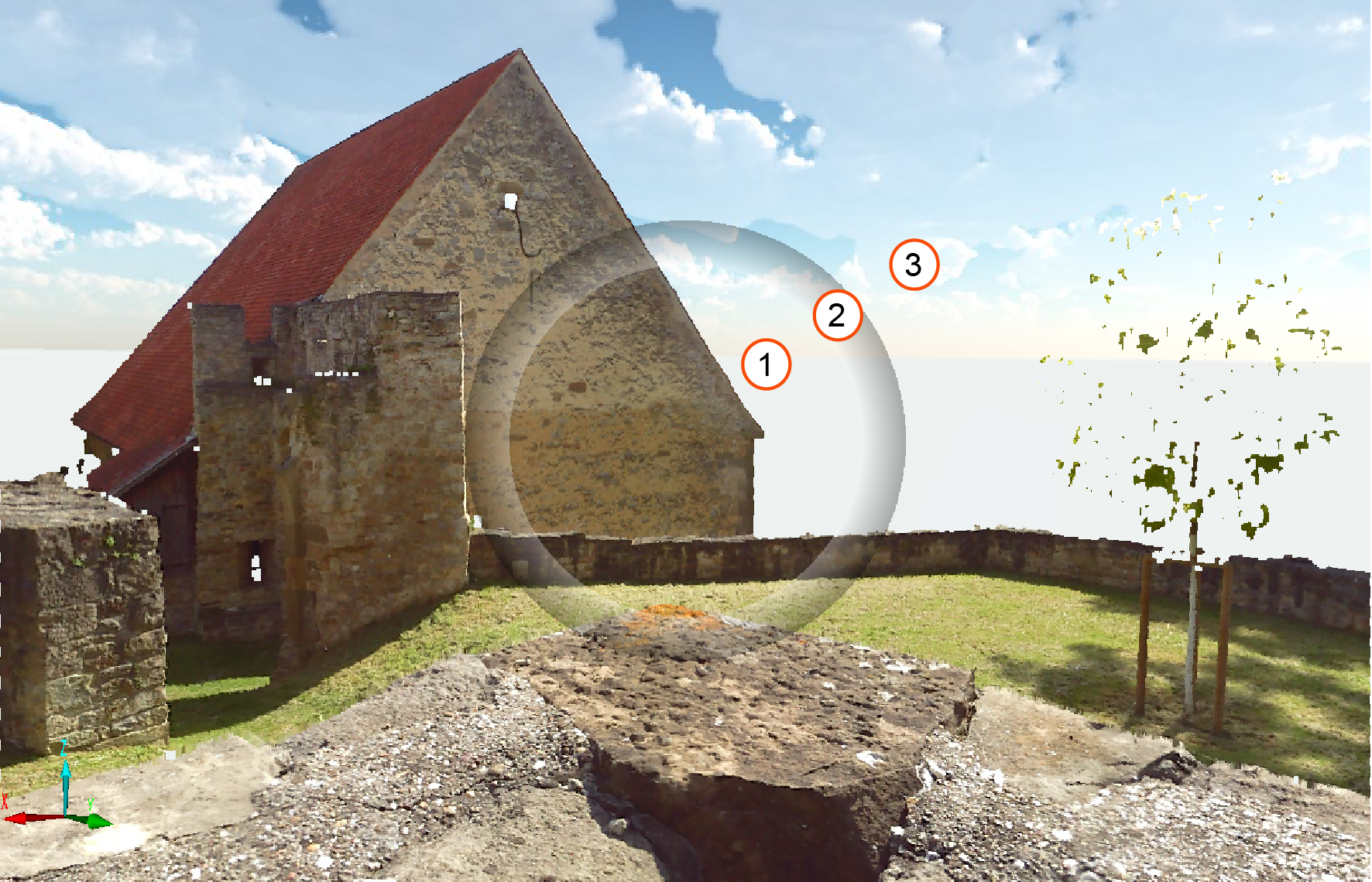
Figure 4-7 3 Zone navigation
-
Fly Mode: Activated when the cursor is in the inner of the ring.
-
Roll Mode: Activated when the cursor is on the ring.
-
Examine Mode: Activated when the cursor is in the outer area of the ring.
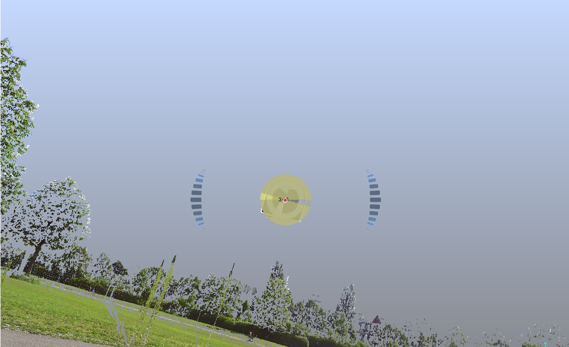
Figure 4-8 Scenery with Roll mode
To do this, click the ring and drag in any direction. A circle will appear in the middle of the view, indicating the rotation angle.
Fly Mode 
The Fly Mode of the observer-based navigation simulates flying through the 3D world.
- Click and drag the 3D view with the mouse to simulate a flight around the scanner’s position.
- The cursor keys left, right, up, and down turn your head to the left, the right, forward, and backwards.
- The keys page-up and page-down move you up and down.
- In addition, you can press the shift key to accelerate these movements.
Pan Mode

There is no turning available in this navigation mode. Mouse movements are interpreted as observer movements.
Walk Mode 
The Walk Mode of the observer-based navigation is similar to the fly mode but you can only travel along the XY plane. This is useful if you want to stay at the same height while navigating.
Camera Modes
Click the camera modes button to change from Orthographic to Perspective mode and vice versa.
Perspective
The 3D view displays the scan points and objects with the correct perspective - objects of the same size appear smaller with increasing distance.
Orthographic
The 3D view displays objects of the same size identically, regardless of how far away they are. This type of representation is common in a CAD systems.
View All
Not available in the quick view.
Changes the position of the observer in such a way that a view on all the objects is achieved.
Predefined Views
Changes the position and viewing direction to view the complete scene from top, bottom, right, front, back, or in an isometric view.
Double-click a scan point to fly to a location. SCENE will then zoom into the scene, close to the selected scan point. Cancel the movement by clicking and moving the view with the mouse, or with the respective keys.
Center of Rotation
The center of rotation (the rotation point) is somewhere in the 3D world. It is set automatically by some functions, for example, when using the object-based navigation.
In the Fly mode, the center of rotation is set to the position of the observer.
To set it manually, click the Set rotation point button, then click the scan point or object.
Last Camera Position
The Last Camera Position button moves camera to the last camera position.
Align Camera on Point
Click the Align Camera on Point button, then pick a point in the 3D view to align the camera position to an estimated surface. The center of rotation will be set to the picked point.
Supersampling
Switches supersampling on or off.
Supersampling renders the point cloud with a resolution higher than the resolution of your screen, and then shrinks the point cloud to fit the screen resolution.
This reduces anti-aliasing effects and gives the point cloud a smoother visual appearance. Fine and filigree structures look sharper, and stray points will appear less annoying. Set the resolution of the initially rendered point cloud compared to the screen resolution by selecting one of the options 2x2, 3x3, or 4x4.
For example, selecting 2x2 means that the point cloud will be rendered with a resolution that is 4 times the resolution of your screen.
-
Objects like walls might appear transparent when using small point sizes in combination with supersampling.
-
High supersampling resolutions like 4x4 require large amounts of graphics card memory.
Gap Filling
Switches gap filling on or off.
If switched on, it will fill gaps between scan points that are physically close to one another. Gap filling can be defined as a predefined setting.
Backface Culling
Switches back face culling on or off.
Backface culling is a rendering process that hides the backface of points. For example, this is helpful for indoor captures, see also figure below. If you zoom out, you would usually see the backface points of the capture. Enabling this feature, will let you see the front face of the captured points without visual obstruction by the backface points.
This feature only works under the following conditions:
-
Only for mobile scans.
and
-
Project created with SCENE 2025.2.
or
-
You deleted and redid the scan point clouds and the project point cloud.
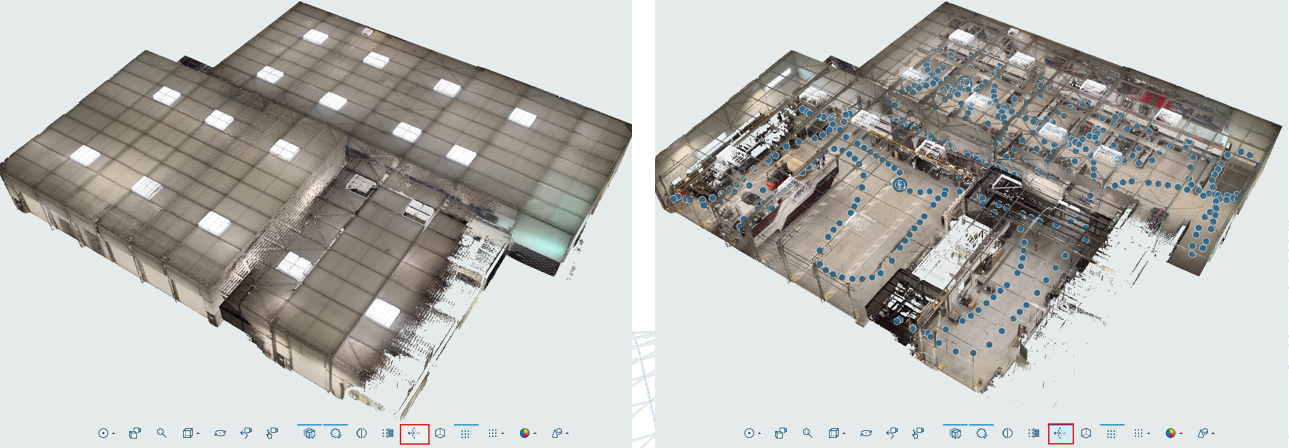
Figure 4-9 Backface culling deactivated vs. activated
Clear View
Switches Clear View on or off. Clear View can be defined as a predefined setting.
Toggle Clipping Boxes
If there are Clipping Boxes (3D view) placed in the 3D view, you can switch these on or off with the Toggle Clipping Boxes button.
Point cloud visibility
Switches the Point cloud visibility on or off. If switched off, other settings, e.g., clipping boxes, remain active.
Point Sizes
Toggles adaptive point size mode, and switches through three different point size settings.
Adaptive
When Adaptive point size is active, the displayed size of each point adapts to its distance to the observer. The closer a point is to the observer, the larger it gets.
If adaptive point size is deactivated, points always are drawn with the same size in pixels. They get displayed with the same size on screen, no matter how distant from the observer they are located.
The three point size buttons scale the size of the points on the screen and can be used to influence the density of point visualization.
The 3D view is used just like the other views. In addition, in the 3D view you can position yourself at arbitrary positions in space and look at the scan points and CAD models. The mouse is used to define the turning movements you want to perform, and with the keyboard you define the actual movement in space.
Coloring
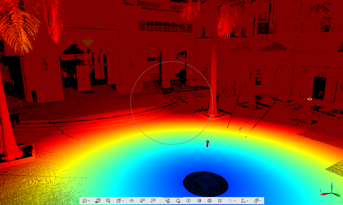
Figure 4-10 Distance Coloring |
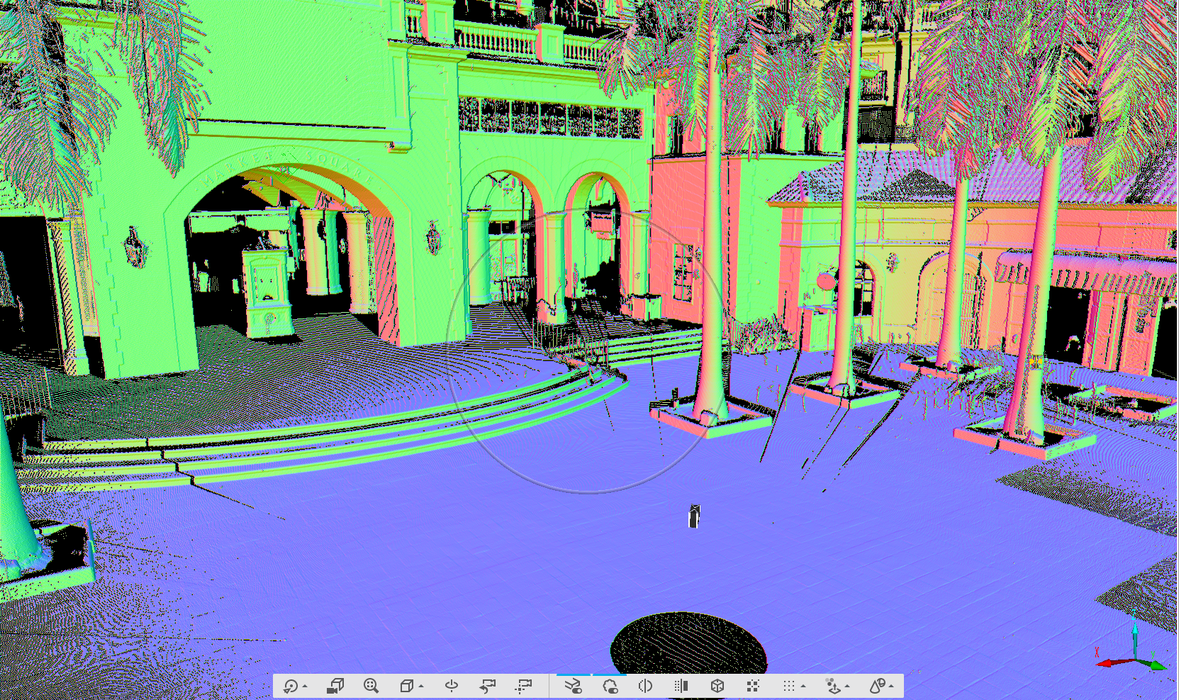
Figure 4-11 Normal Coloring |
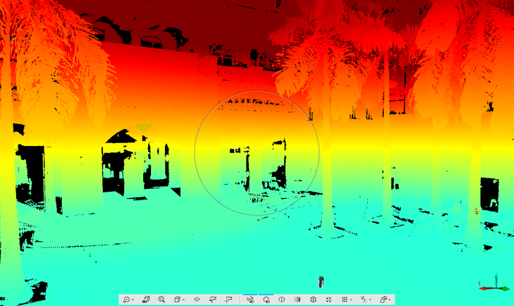
Figure 4-12 Z-Axis Coloring |
This feature temporarily changes the color of the points in the point cloud according to their coordinates in the scan. This can highlight features that are difficult to see in the point cloud, such as showing whether a surface is perfectly flat, or showing if objects that are far from each other have similar or different elevations. Use the coloring modes shown below with the settings found in Coloring (3D View only) and Shading (3D View only) where you can adjust color palettes, coloring ranges, shading strength and other parameters used in coordinate coloring.
Normal Coloring: A geometric normal is a vector that is perpendicular to an object. Normal coloring changes the color of the points depending on the direction of the point's normal. This means that mostly flat, uncurved surfaces will be one color, while surfaces that are curved will have more colors.
XYZ Axis Coloring Mixes all R, G, B (X,Y,Z) color channels.
X Axis Coloring: changes the color of the points based on their position in the X axis.
Y Axis Coloring: changes the color of the points based on their position in the Y axis.
Z Axis Coloring: changes the color of the points based on their position in the Z axis.
Distance Coloring: changes the color of the points based on their distance from the reference object.
Color by Time: only for Orbis mobile scans. Changes the color or the individual scans according to the time when they were captured.
Intensity: changes the color of the points to grayscale (intensity) (available since SCENE 2025.0).
Original Colors: Removes the coordinate coloring and shows the points with the colors they originally had after the scan was processed and colorized.
Point Shading
Shading makes some points darker in an attempt to simulate shadows to increase the sense of depth and make subtle features more visible. You can select strong, light, or no shading.