General View Settings
|
1238888 |
Click the  icon in the toolbar on the right side to open the General View Settings form.
Live View
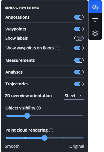
Figure 1-42 General View Settings
The following general view settings are available in the live view:
The General View Settings menu contains the following entries in the live view:
Hide or Show Objects
Show or hide information of the objects mentioned below. This is helpful in point clouds with a lot of objects to increase the visibility of a particular object type.
-
Annotations: Hides or shows annotations.
-
Waypoints: Hides or shows waypoints. You can make more settings for waypoints, see below.
-
Measurements: Hides or shows measurements.
-
Analyses: Hides or shows the coloring added by the point cloud analysis, see Run a Point Cloud Analysis.
-
Trajectories: Hides or shows the trajectory. Note that the waypoints of the currently selected trajectory remain visible.
Waypoints
-
Show labels: Show or hide labels.
-
Show waypoints on floor: If you activate the switch, waypoints are displayed on the floor with a predefined offset.
If you deactivate the switch, waypoints are displayed at their actual elevation. -
Colorize - Custom: If you activate this switch, the default colorization is used. You can change the custom color on the Dashboard in the workspace settings, see Settings: General.
-
Colorize - By elevation: If you activate the switch, waypoints will be displayed with different colors according to their elevation. Note that this option is only available if the elevation difference is greater than 1 meter.
-
Colorize - By capture date: If scans were captured on different dates and at least one day apart, you can colorize the waypoints according to their capture date.
-
HoloBuilder colors: Shows the waypoints in the colors that were used in the HoloBuilder WebEditor.
For the options Colorize by elevation and Colorize by capture date, a scale showing the color gradient is displayed at the lower right side of the screen. Unconnected scans are displayed with a yellow rim.
For more detailed information on defining waypoint colors, see Coloring Options for Waypoints.
2D overview orientation
-
Sheet: If you add a sheet, it is aligned to an existing sheet. In this default view, it may occur that the sheet is not 100% square or flat.
-
Project: If you add a sheet, it is aligned to the project coordinates.
This setting also affects the camera orientation in the 2D view when sheets are displayed. For more information on adding sheets, see Add, Edit or Delete Sheets in Existing Projects.
Object visibility
Use the slider to increase or decrease the distance at which objects, for example annotations and measurements, become visible.
Point cloud rendering
Use the slider to adjust the visual appearance of point clouds. The following options are available as positions on the slider.
-
Smooth: Optimized for a smooth fly-through experience. Details may appear blurred and flattened out, especially on SLAM data. Use this option for sparse point clouds.
-
Balanced: Good fly-through experience. Details appear sharper, especially when more points are loaded.
-
Sharp: The navigation is smooth. Details are enhanced by outlining them. This option works well for SLAM data.
-
Sharpest: Maximum sharpness of detail. The fly-through experience is noisy. This option works well for detailed annotations and measurements when the camera is not moving.
-
Original: Shows the original point cloud data without any special effect.
3D Model visibility
Use the slider to configure the minimum distance at which the active model will be visible in the current 3D scene. Note that this setting is only visible if the project has a 3D model and it only affects the walkmode view.
Draft View
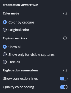
Figure 1-43 Registration mode settings
The following general view settings are available in the draft view:
Capture markers
Capture markers and waypoints in this context are currently scans only.
-
Show all: All markers are displayed including markers of waypoints that may not be visible because they are hidden below connections or other markers.
-
Show only for visible captures: Only the markers of visible waypoints are displayed. Markers of waypoints that are hidden below connections and other waypoints are not displayed.
-
Hide all: All markers are hidden.
Registration connections:
-
Show connection lines: If you activate this switch, the connection between waypoints are shown. Activating this switch will enable the Quality color coding switch.
-
Quality color coding: If this switch is activated, the connections are colored based on the registration quality, i.e. green for good quality, yellow for medium quality and red for poor quality. If this switch is deactivated, the connection lines are displayed gray.
Color mode
-
Color by capture: Each waypoint and the scan it represents get an individual color to distinguish it from the other waypoints and scans. Coloring the scans in different colors makes it easier to identify which points belong to which scan.
-
Original color: The waypoints are displayed in their original color to provide a first impression of the original capture colors (without color balancing).