Symbol|Model Tool Panel
Options for different types of symbols vary. For example, there are more options for a vehicle symbol than there are for an object such as a paper bag. Following are the most common Symbol tool panel options.
 Materials PBR Materials PBR
|
Customize the texture of the object. See PBR Materials. | |
 Layer Manager Layer Manager
|
Select a layer or add a new layer for the object. | |
 VRT Settings VRT Settings
|
||
 Damage Damage
|
Apply damage to the vehicle. | |
| Model Name | Displays the model name. Click inside the field to change the name. | |
| Animate |
Animate the symbol. See Animating a Symbol. |
|
| Source |
Lists the source image for the symbol. |
|
| Position/Size/Orientation | ||
| X, Y, Elev Z |
Change the symbol’s axes positional values by entering new values or by using the dial arrows. |
|
| Length, Width, Height | Change the symbol’s size values by entering new values or by using the dial arrows. | |
| Yaw, Pitch, Roll | Change the symbol’s values by entering new values or by using the dial arrows. | |
| Model Settings | ||
| Follow Terrain | Have the symbol follow the pattern of the terrain. | |
| Flip X|Flip Y |
Flip the model on the X or Y axes. |
|
| Aspect Lock | Locks Height and Width settings so that they cannot be adjusted separately. | |
| Lock Orientation | Toggle this option on to lock the symbol’s orientation on the grid. | |
| Render 2D Image | Convert the image to a line drawing. | |
| Show Resize Grips | Display or hide grips that you can use to resize the model. | |
| Pivot Offset | Adjust the offset from the placement point. | |
| Show Vehicle Specs | In some cases, models do not have the exact specs for the vehicle. Use this option to adjust the dimensions of the model to match the vehicle specs objects. You can manually adjust the model, or have the software automatically adjust the model to match up with the vehicle specs model. | |
| MassZone Properties | View options for the MassZone feature. See Understanding How FARO MassZone Works. | |
| Tools | ||
| Suspension |
Show vehicle body reactions due to suspension effects during the animation.
Adjust the following settings: Suspension Factor - Adjust the 'strength' of the suspension reaction. Higher values result in more pronounced action. Suspension Recovery - Adjust the suspension's recovery strength. Higher values result in a faster reset/recovery response. |
|
| Tools | ||
| Damage |
Open the Damage tool panel, which includes options that allow you to recreate the damage to an object. See Adding Damage to a Symbol. |
|
| Symbol Parts |
Open the Symbol Parts tool panel, which allows you to customize the parts that comprise the symbol (if applicable). See Symbol Parts Tool Panel. |
|
| Edit Lights |
Adjust lighting effects. See Editing Lights With the Lighting System |
|
| Link Symbol |
Link the symbol to another symbol. |
|
| Edit Model | Open the model editor to make further edits to the symbol. |
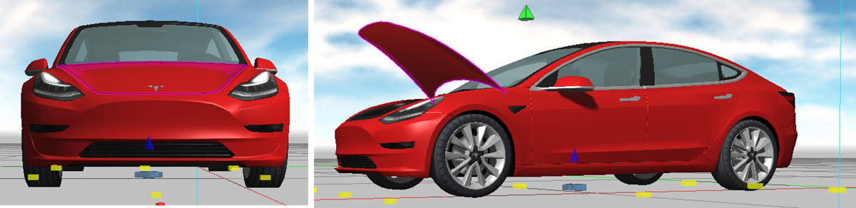
2D Symbol Rendering
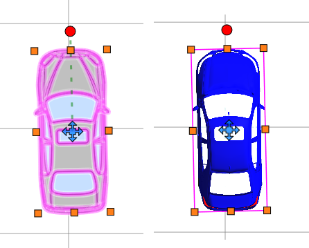
When you select a 3D symbol in 2D mode, the symbol renders with the 3D symbol’s color and markings. The 2D symbol display matches the top-down view of the 3D symbol, even if yaw and pitch are adjusted.
Follow these steps to adjust rendering on a 2D symbol:
-
In 2D mode, place a vehicle symbol.
-
With the symbol selected, click Orientation/Settings.
-
Toggle off Render 2D Image to change the 2D image to a line drawing; toggle it on to render it with 3D coloring.
-
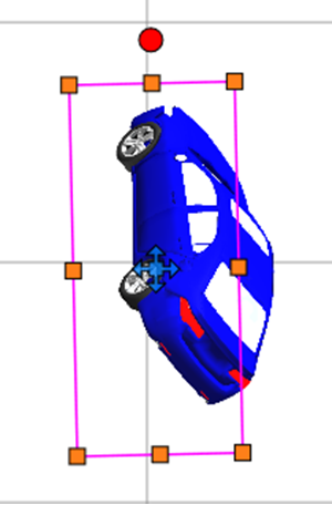
With Render 2D activated, enter Roll (deg) and Pitch values. The symbol adjusts to the selected angle.
-
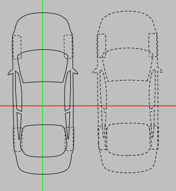
Click Convert to Dashed to convert the object's lines to dashes.
-
Optionally, you can link a symbol to a different image by clicking Link Symbol. Enter the search value and select the desired image. Now when Render 2D is deactivated, the selected symbol displays.
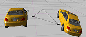
Symbol Align to 3 Points
You can align a symbol to a plane using three points. This is a common task when working with point clouds.
Follow the steps below to align a symbol to a plane.
-
Insert or select a symbol.
-
Right-click the symbol.
-
Select Symbol Align-3 Points.
-
Click three points to form a plane, either in point cloud, or the surface of an object, or the ground plane. The symbol snaps to establish the plane.
Symbol Parts Tool Panel
Customize the parts that comprise the symbol (for supported symbols).
The Symbol Parts tool panel lists all of the individual parts in the symbol.
Select the part that you would like to modify, and choose from the following options.
| Advanced Material |
Customize the surface of the selected area with the PBR tools. See PBR Materials. When PBR is off, select colors and Emissive settings from the color palette. |
| Transparency | Use the slider to adjust the transparency of the part. If you want to partially hide the part to show the next layer, lower the Transparency setting. |
| Smoothness | Adjust the smoothness of the texture of the part. |
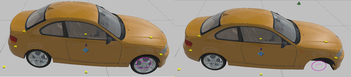
| Part/Group Rotation |
Adjust the rotation for parts that support this feature. On supported vehicles, use the slider to open doors, hoods, and deck lids. Select the part from the list, or select the part directly in the image. Unsupported vehicles display with "Part not configured for rotation".
Following are links to videos that pertain to this feature:
|
| Paint Color | Adjust the color of the paint. |
| Hide Part |
Show or hide the selected part.
You can hide a part from the vehicle and show the part at another location in the drawing. Select the part from the parts list, right-click the part, and choose Save Selected Part as Model. See the following videos: Hide selected model parts
|
| Terrain | Enable to have the vehicle follow the terrain. |
| PBR | Enable or disable PBR. |

Editing Lights With the Lighting System
Some symbols, such as vehicles, include customizable lighting. You can convert any object to a light; such as lamps, non-lit vehicles, or objects that aren’t typically lights.
Customization options for symbols with light systems include:
-
Light types
-
Light styles
-
Switch lights on or off
-
Turn blinking on or off
To add or edit a light system:
-
Select and place a symbol.
-
Right-click the symbol and from the context menu, select Setup Lights.
-
For symbols that include light systems, an Edit Lights option appears in the Symbol tool panel.
-
Configure options in one of the Light Setup tool panels, and then save the updated symbol. Light Setup Tool Panel
-
The symbol displays with the selected light options.
Light Setup Tool Panel
When you add lighting to a symbol, one of the following tool panels displays:
-
The Lights tool panel displays for symbols that include a lighting configuration. This tool panel is pre-configured with the parts of the symbol where lighting can be applied. For example, for vehicles, you can easily configure lighting for all of the exterior lights.
-
The Light Setup tool panel displays for symbols that do not include a lighting configuration. You must configure the parts of the symbol to light, along with other details.
You can configure the following properties in one or both tool panels, as indicated:
| Symbol Parts |
(For symbols that do not have lighting configured.) Lists the parts that comprise the symbol. Select the parts on which to apply lighting. |
| Is Light |
(For symbols that do not have lighting configured.) Make the selected symbol part a light. |
| Light Name |
Apply a name to the light. |
| Light On |
Illuminate the light. |
| Light Template |
(For symbols that do not have lighting configured.) Use the dropdown to select from the available templates. |
| Light Style |
Use the dropdown to select from available lighting styles. |
| Color On |
Select the lighting color. |
| Blinking |
Apply a blinking effect to the light. |
| Blink Frequency |
Enter the rate at which the light blinks. |
| Inner Cone |
Increase the center area of the light. |
| Outer Cone |
Increase the outer area of the light. |
| Range |
Enter a value for the range to which the lighting effect extends. |
| Intensity |
Use the slider to adjust the brightness of the light. |
| Point Cloud Intensity |
Use the slider to adjust the saturation level of the point cloud surrounding the light. |
| Offsets |
(For symbols that do not have lighting configured.) Adjust the X, Y, and Z axis offsets for the lighting pattern. |
| Yaw |
(For symbols that do not have lighting configured.) Adjust the yaw position of the lighting pattern. |
| Pitch |
(For symbols that do not have lighting configured.) Adjust the pitch of the lighting pattern. |
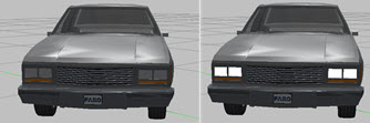
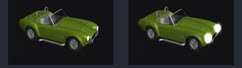
Light Bloom
You can add a light bloom (glow) around the light source to add realism to any light system.
To activate light blooms on all lights.
-
Click Preferences > Display.
-
Under Advanced, select HDR Light Bloom.
The following image shows light boom off/on.
