 Cloud Tools
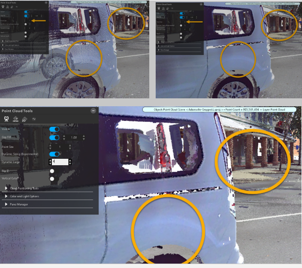
Options in Cloud Tools allow you to adjust the appearance of the point cloud. Open the Cloud Tools panel from the Point Cloud ribbon. This tool panel does not open when you click the point cloud.
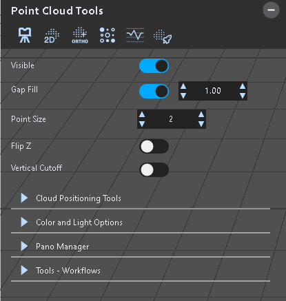
The Cloud Tool panel includes the following options:
 Launch Scan Manager Launch Scan Manager
|
Launch the Scan Manager. See Scan Manager and Scanner Tool Panel. | |
 Printable 2D View Printable 2D View
|
||
 Create Ortho Image Create Ortho Image
|
Launches the workflow that guides you through creating a workflow image. | |
 Ortho Density Map Ortho Density Map
|
Launches the workflow that guides you through creating an ortho density map. | |
 Create Profile Line Create Profile Line
|
Launches the workflow that guides you through creating a profile line. See Creating a Point Cloud Profile Line. | |
 Create Point Cloud Model Create Point Cloud Model
|
||
| Visible | Hide or show the point cloud. | |
| Gap Fill |
Fill in the gaps between points on a point cloud to make the point cloud display with a smoother appearance. Gaps in point clouds are the result of missing or incomplete in the point cloud scan.
|
|
| Point Size |
Adjust the size of points in the point cloud. Increase or decrease the size of the points to improve the point cloud's appearance.
|
|
| Dynamic Sizing |
Adjust the individual point size based on the inverse distance from the camera. Point Size - Adjust points for a zoomed-out view of the point cloud. Dynamic large - Adjust points for close-up views.
|
|
| Flip Z |
Use Flip Z to flip your point cloud vertically. This tool is useful in many situations. For example, you can more easily re-draw a roadway that has overhanging trees, or you can easily trace the wall outlines of a building without the roof and furniture getting in the way.
|
|
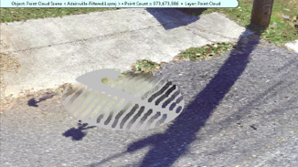
| Vertical Cutoff |
Use Vertical Cutoff to clip overhanging obstacles such as trees, roofs etc so you get a clearer view of the underside. Set the height (in world space coordinates) at the point to start the cutoff.
|
|
| Cloud Positioning Tools |
Cloud positioning tools includes options for positioning the point cloud in the drawing. See Positioning the Point Cloud
|
|
| Color and Light Options | ||
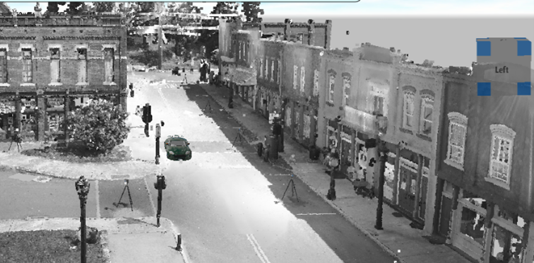
| Greyscale |
Display the point cloud in greyscale to display greater contrast.
|
|
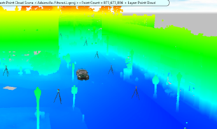
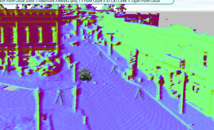
| Height Map |
Convert the point cloud to gradient colors scaled by the height of the point cloud.
|
|
| Invert Color |
Switches all colors to their inverse. (for example, dark colors become light).
|
|
| Enhance Mode |
Enhance Mode is useful for dark scenes, or scenes that lack color variation. This mode roughly shows the view-dependent variations on surfaces within the point cloud.
|
|
| PC Lighting |
Adjust lighting for the point cloud. See Customizing Point Cloud Lighting. |
|
| Cast Shadows | Use the Cast Shadows tool to add shadows to items on the point cloud. See Point Cloud Shadows. | |
| Brightness |
Adjust the brightness of the point cloud.
|
|
| Contrast |
Adjust the contrast of the point cloud.
|
|
| Opacity |
Adjust the opacity of the point cloud.
|
|
| Pano Manager | You can view the point cloud in pano-mode, which sets the panoramic image from the FARO Focus scanner as the background. Pano images are only available with scans obtained from a FARO-supported scanner like the FARO Focus. Pano images are not included in scans taken with the FARO FreeStyle, or from scans created via a merge or conversion process. For a description of options under Pano Manager, see Viewing Point Clouds in Pano Mode. | |
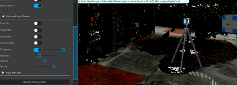
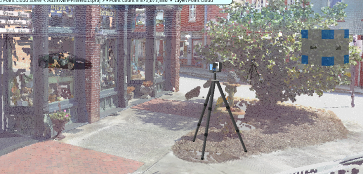
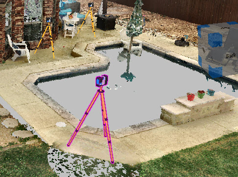
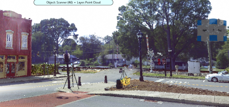
| Show Scanners |
Show the positions of the scanners in the point cloud (for point clouds created from FARO scanners). Merged or converted point clouds do not include scanner position data.
Select a scanner to modify options for it. Double-click a scanner to switch to Pano-View mode. In Pano-View, the panoramic image from the scanner is used as a background to your 3D environment.
|
|
| Show Pano View | ||
| Pano Virtual Depth Mode | ||
| Scan to View | ||
| Grayscale (Reflection) Pano | Creates grayscale based on intensity values from the laser (for lasers that capture intensity values). | |
| Tools - Workflows | Launch workflows with guided instructions for the listed commands. | |
|
|


Point Cloud Shadows
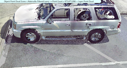
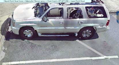
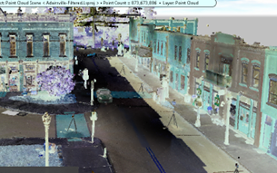
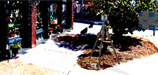
Under Color and Light Options, enable Cast Shadows to add shadows from buildings, light poles, trees, and other structures.
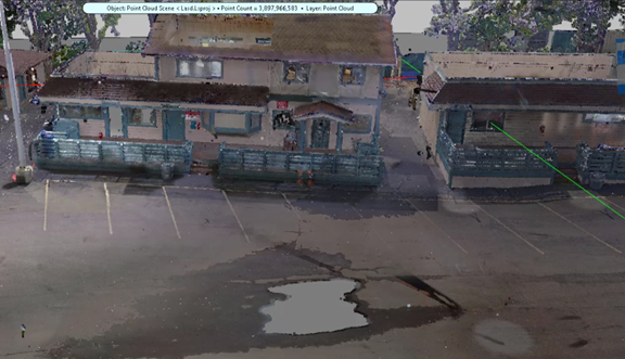
Without shadow casts
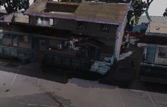
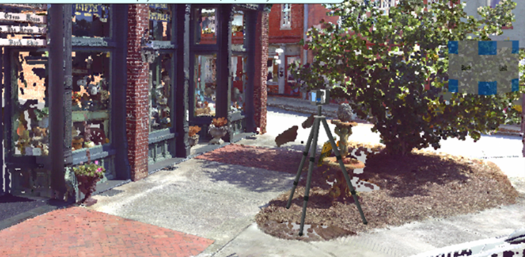
With shadow casts
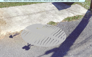
Use the following settings to improve the appearance of the shadows.
Adjust Shadow Cast Point Size allows you to increase or decrease the shadow's point sizes.
Adjust Shadow Cast Fidelity to change the sharpness of the points in the shadow. Depending on other lighting settings, you may need to increase or decrease this setting.
The shadows generated with the tool use the sun/moon positions in the Sky-Environmental Lighting settings. See Sky. If you change the sky settings, the shadows created with the tool may take a few moments to generate.
Shadow Casting also requires a non-point cloud object to define the bounding area of the diagram. Draw a rectangle that encompasses the area of the point cloud before you use this feature.
