Processing Scan Data In Zone

|

|

|

|

|

|

|

|

|

|

|

|

|

|

|

|
| Scan | Register | Clipping Box | Ortho | 2D Diag | 3D Diag | Fly-Thru | Zone2Go |
Use this workflow to process scan data directly in FARO Zone 3D. This process requires no additional software between scanning and processing the images in FARO Zone 3D.
Scan the data
-
Scan the object with a FARO Focus scanner.
-
Copy the scan data folder from the SD card to your computer.
Register the point cloud in FARO Zone 3D.
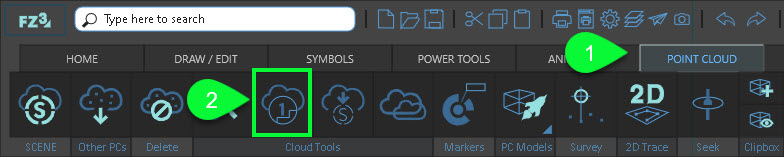
① Open the Point Cloud ribbon.
② Click the Point Cloud Registration tool.
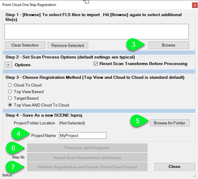
③ Browse to, and open the RawScans or Scans folder and <Shift + click> or <Ctrl + click> to select all of the individual scans to register.
Each individual scan may reside in its own folder. In this case, you need to copy each .fls scan file individually.
④ In the Project Name field, type a project name.
⑤ Click Browse for Folder and select or create a new project folder that will contain all of the project files.
⑥ Click Process and Register and then preview the point cloud.
⑦ Click Confirm Registration and Create Point Cloud Project.
Crop the image with a clipping box
1. Show only the part(s) of the point cloud you want to work with by hiding all unwanted points.
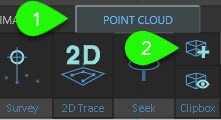
① Open the Point Cloud ribbon.
② Click Clipping Box.
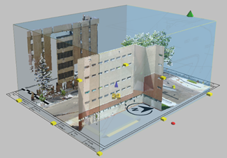
2. Use the grips to size the clipping box.
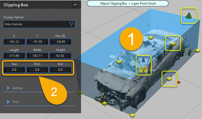
① Use the grips to size the clipping box.
② Use the coordinates to adjust the position of the box.
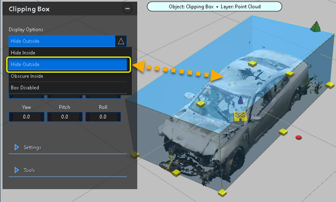
3. From the Display Options, select Hide Outside.
4. You can create multiple clipping boxes to clean up the scene.
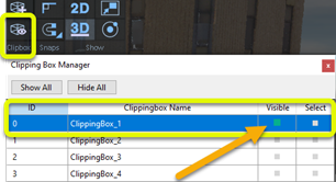
5. You can hide the clipping box.
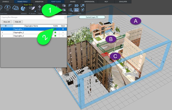
① Open the Clipping Box Manager.
② Disable Visible to hide the clipping box.
Create the Ortho image.
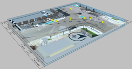
Ortho images are real world scale, and can be used as the basis for a 2D diagram. Create a flat, top down, orthographic image from the point cloud for quick 2D diagramming.
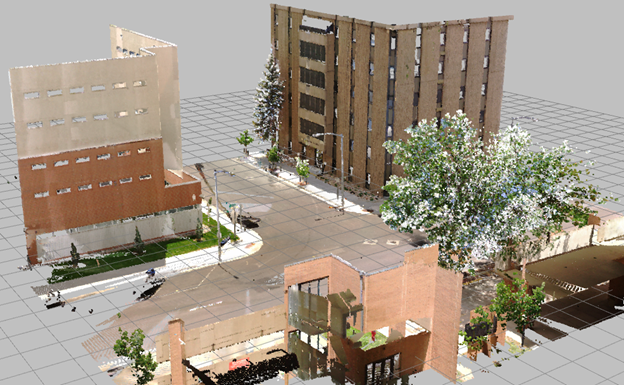
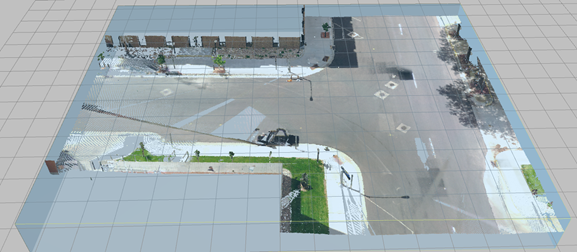
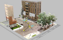
1. Display the main clipping box and adjust its size to define the orthographic image. In this example, we will adjust the clipping box's height to hide the trees, and adjust the length and width to highlight the intersection.
2. With the clipping box selected, click Create Ortho Image from the Clipping Box tool panel.
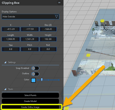
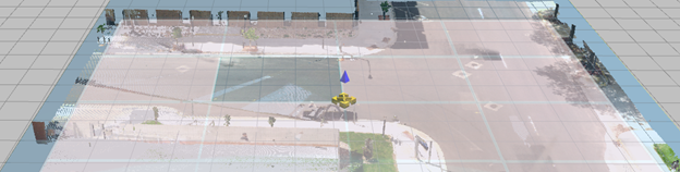
3. You are prompted to save the diagram as an fzproj (FARO Zone Project). After you select a folder and a name for the project, the image is generated as a high-resolution tiled image.
4. Hide clipping boxes with the Clipping Box Manager, and disable point cloud display from the Point Cloud tool panel.
-
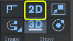
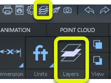
Enable 2D mode from the ribbon.
-
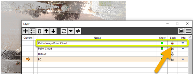
Open the Layer Manager and lock the Ortho image layer. This makes it easier to draw on top of the image without inadvertently selecting it.
-
Draw line work by tracing over the image.
a. Draw using lines, curves, arcs, circles, etc…
b. Set color and thickness to help them standout while you’re drawing on top of the image.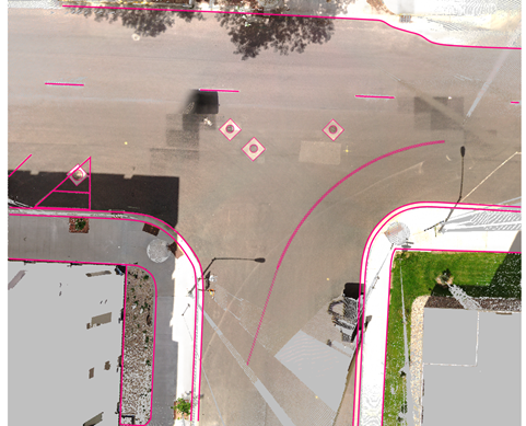
Save your project often. If an issue occurs, you can re-open the drawing or use the Backup/Restore option located on the File pull-down menu.
-
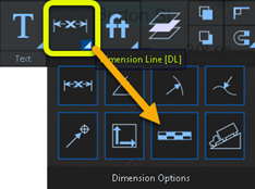
Dimension key elements of the drawing.
 See Dimension.
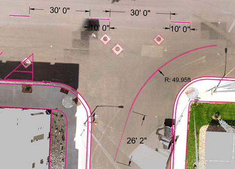
-
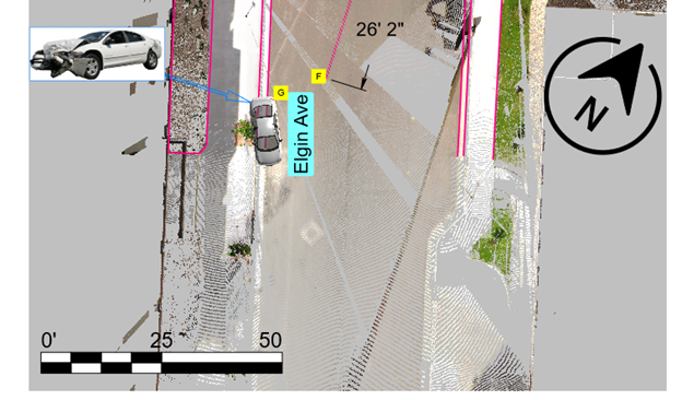
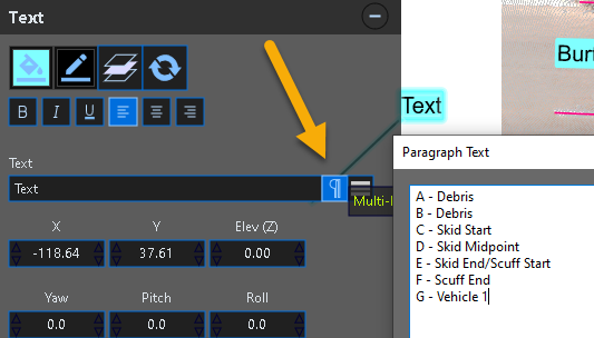
 Add annotations such as labels and photos.
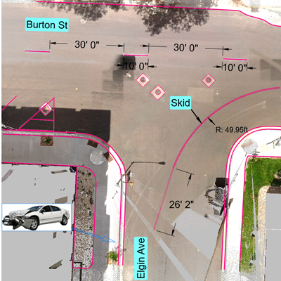
-
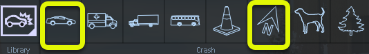
Add symbols, such as a North arrow, and vehicles.
-
Add an Evidence Placard. See Text
After placing the first placard, hit the Spacebar to place another placard. The placard numbers change sequentially as you add them.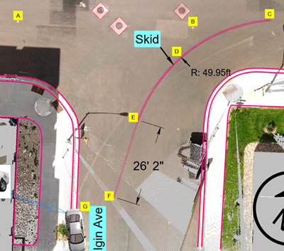
-
Place a Scalebar for reference in the printed document. See Place Scalebar. The Scalebar is on the Dimension menu. You can resize the Scalebar with the grips.
-
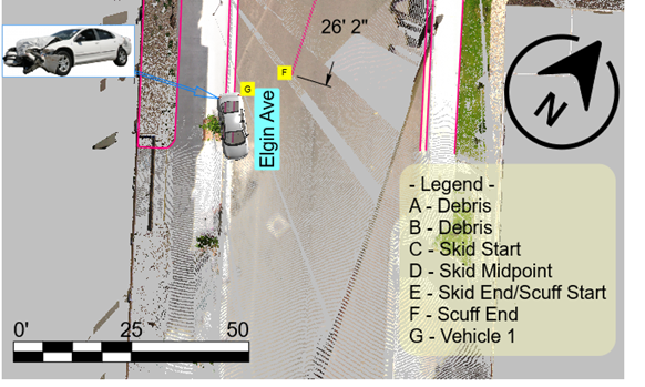
Create a text legend. Use the Paragraph tool to create the legend quickly.
-
Create a form. Finalize your drawing with a form template, or create your own custom form. From the Power Tools ribbon, select Forms. Select and edit the text in the headers. See Forms.
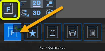
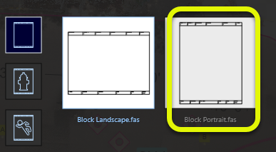
Click on the form template to automatically place it around the drawing.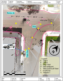
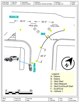
You can also hide the ortho image layer before you print.If you select the entire drawing, you can set the line color to black.
-
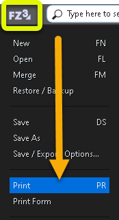
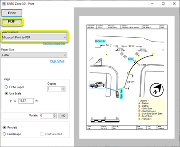
Print to PDF. See Printing.
Create a two-dimensional line drawing from the ortho image
Do visualization work in 3D
1. Switch to 3D mode.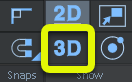
2. Hide the ortho image layer. Displaying the ortho image with the point cloud is optional.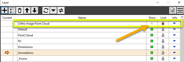
3. From Cloud Tools, enable Visible to display the point cloud.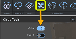
4. From the Clipping Box Manager, enable the main clipping box display and resize it (make it taller) to show the entire point cloud. Hide the clipping box. Look at the pano views.
5. Adjust dimension display options.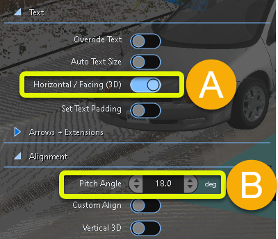
(a) Turn on Horizontal/Facing (3D).
(b) Adjust the Pitch Angle of the dimension off the flat ground plane.
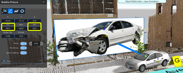
6. Adjust image display options to rotate the image of the crushed vehicle to vertical.
Adjust the model's position if it is obstructed by the point cloud. In the following example, the image was selected, and the Yaw and Roll were adjusted to 90°.
This image was repositioned from behind the point cloud.
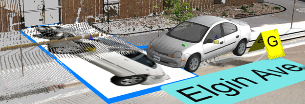
Image Yaw and Roll were adjusted.
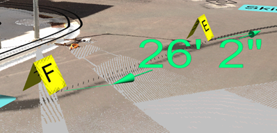
View from a different angle. Note that the dimension text is still facing forward.
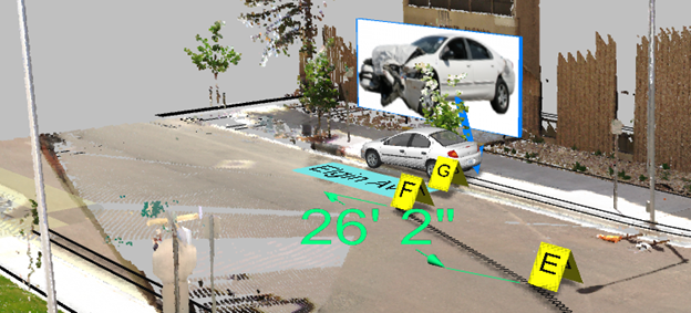
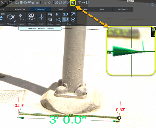
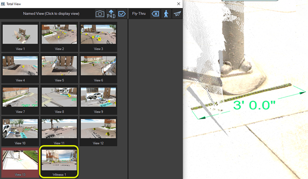
7. Validate the scale by measuring known points in the point cloud.
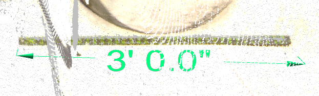
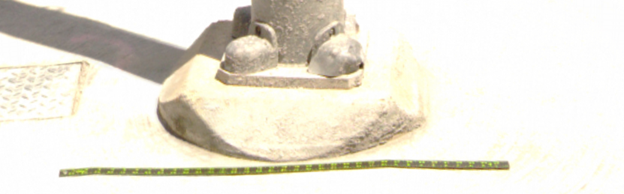
A three-foot (3’) scale was placed at the base of a light pole, so that it would be included in the point cloud scan.
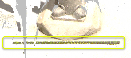
Place a dimension line on the scale in the point cloud.
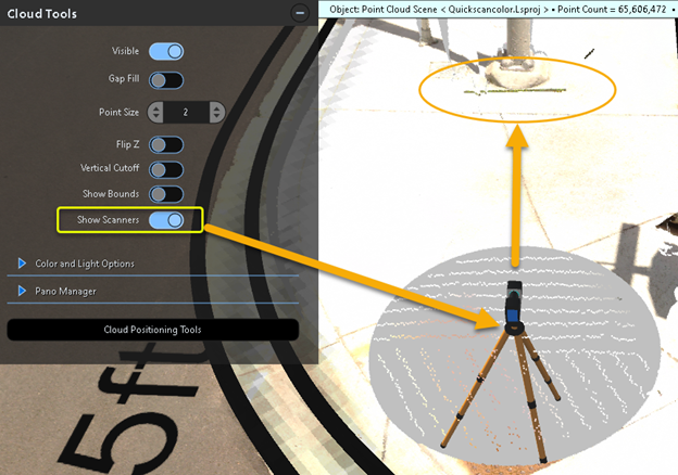
8. You can view panoramic images and point clouds. You can open the pano views generated at each scanner position. This gives you a clearer view of the scene, and allows you to easily pick points. From the Cloud Tools panel, enable Show Scanners.
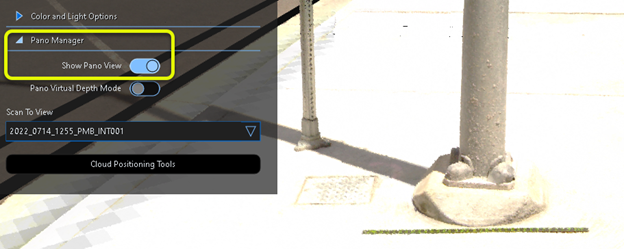
Open the Pano Manager, and enable Show Pano View.
In Cloud Tools, disable the point cloud display to view only the pano image. This may provide a cleaner view.
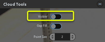
This is the pano view only (with the point cloud display disabled).
You can dimension points by using the panoramic image as your reference. The point cloud is not displayed, but still active.
Select Mag Window from the Quickbar menu to increase the magnification. Use the Dimension tool to pick the endpoints in the Mag Window view.
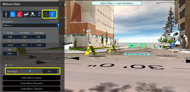
9.Set up  Witness View
Set up a fixed camera position, or "witness view" in the scene. From the Power Tools ribbon, open the Witness View tool.
Place the Witness View icon at the witness' location in the scene.
You can Preview the Witness View and adjust the View Angle from this position. Take a snapshot from this location and save it with your project.
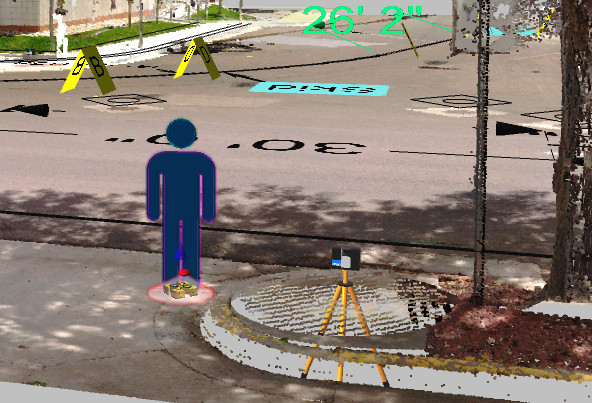
10. Create a simple animation of the vehicle turning the corner.
Place a vehicle model at the starting point of the animation. From here, you will create an animation path.
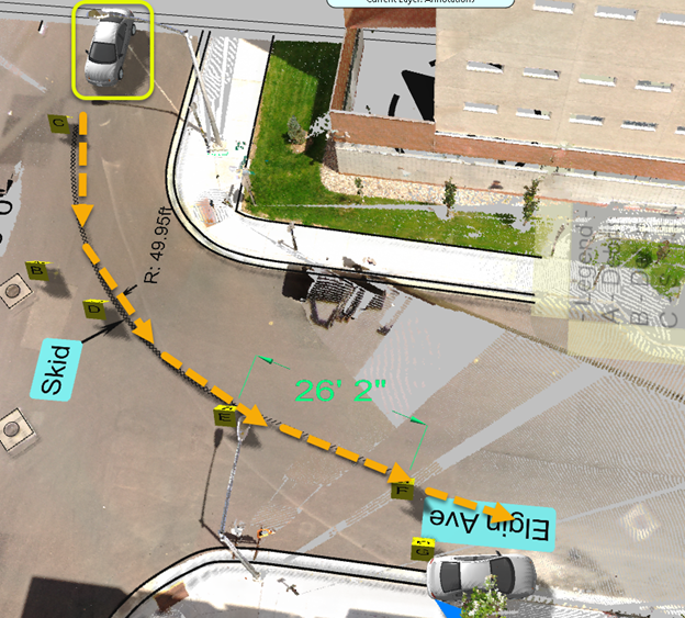
Select the vehicle model and click on the Animate button in the Model tool panel.
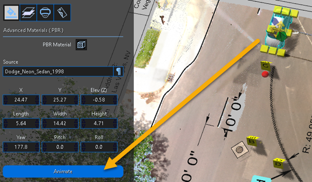
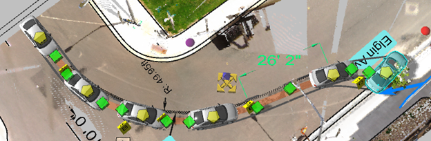
Click points along the travel path to build the animation path. Using the grips, adjust the path to follow the skid marks. You can also adjust the speeds at each KEP (Key Event Point). KEPs include every instance of the vehicle model clicked to create the animation path.
Record and save the animation movie with your project.
Create a movie from the Witness View. Select the Witness icon and then open the witness preview. Record another animation from this vantage point.
In the Dimension tool panel text settings, enable Horizontal/Facing (3D).
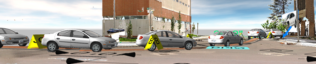
Create a 3D fly-thru movie through the scene.
See Total View.
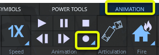
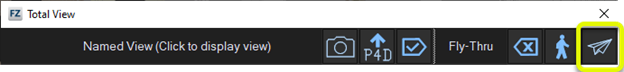
1. From the Animation ribbon, click on the Fly-Thru tool.
![]()
2. Take a snapshot (F2) at each key point that you want to show in the video. All of the snapshots can be rearranged or deleted. You can also click on them to navigate between the views.
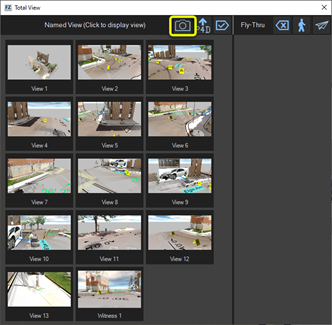
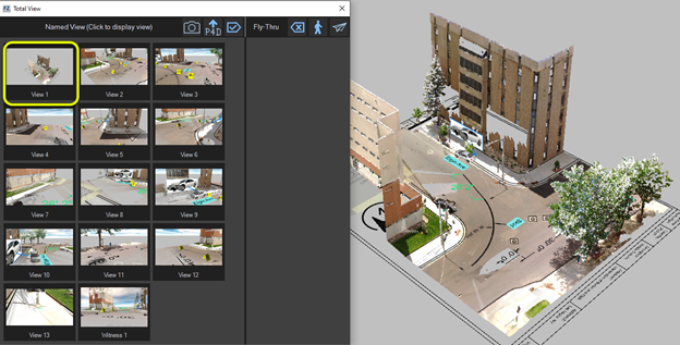
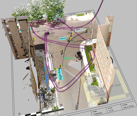
3. Pick a start point for View 1, such as a vantage point that shows the entire scene.
4. For the last snapshot, you may want to show the scalebar.
5. Move the final snapshots into the movie processing bin.
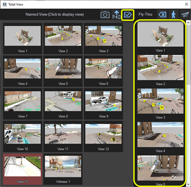
6. Click the airplane icon to automatically build the fly-thru animation path.
7. Set the speed of the fly-thru. Use the KEP Manager to adjust the speeds of the fly-thru segments.
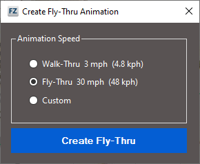
8. Click Create Fly-Thru.
9. Zoom out to see the entire path.
10. Open the Animation ribbon, and save the fly-thru as a movie.

Create a Zone2Go Shareable Package
See Zone2Go
You can use Zone2Go to export and share FARO Zone 3D projects to the storage media of your choice. The Zone2Go viewer is portable and does not require an Internet connection.
You can save the Zone2Go viewer and projects to a USB stick (or other storage device) and view them on a Windows or MacOS device. You can also export to a folder and then copy the folder to a Windows or MacOS tablet, or burn the data to a DVD.
Annotate items that you want to include in the Zone2Go package, and then add the links to the fly-thru.
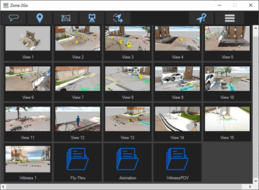
1. From the Home menu, open Zone2Go.
All of the data in the project displays. This data includes snapshots taken for the fly-thru, animation movies, and Witness View snapshots.
2. Use the Annotate tool in the Zone2Go menu to link animation movies, reports, photos, etc. to the overall map view produced by Zone2Go.

3. From the project folder, find the items to link. In this example, we will add links for the animation movies saved for the car, the fly-thru, and a witness pov movie.
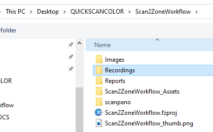
4. Place the link icon for each movie in the desired location.
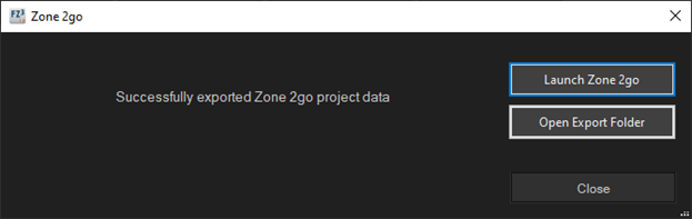
5. Click Export Zone2Go to build the Zone2Go package.

When the Zone2Go project completes, the dialog displays with options to launch the project for review, and open the project export folder.
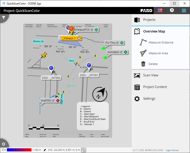
6. Zone2Go lists all available projects. Click on the project to view.
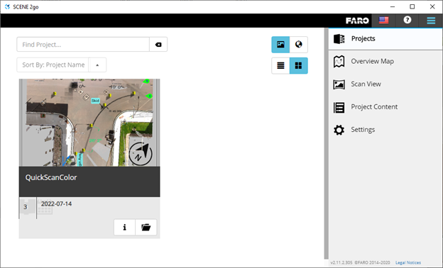
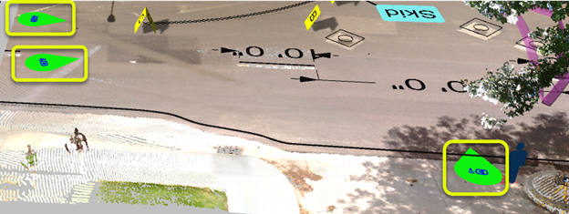
The overview map of the project shows all the links you can use to view animation movies, scan locations, and other linked data.
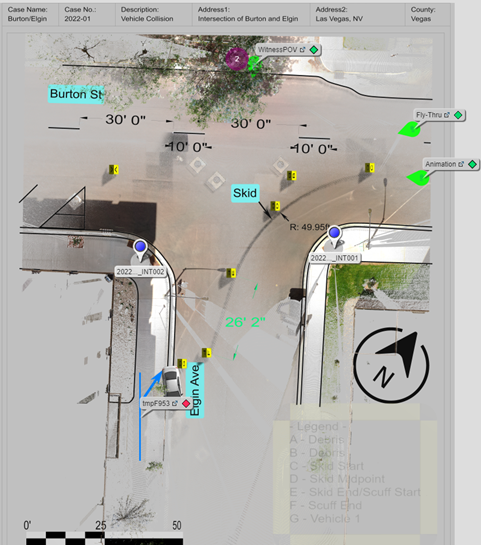
If you want the diagram to display more prominently, you can hide the point cloud before you create the project.
