Capture Tab: Icons and Elements in the Project Structure View
|
123-2026-02-27-888 |
The project structure view is available in the 2D View in the 3D view and in the walk mode view. You can collapse and expand the project structure view by clicking the triangle icons at the top left of the screen.
It contains all elements of your project in the tree view as well as the available actions in the three-dots menu. The elements in the tree view are displayed with icons that provide information of the content.
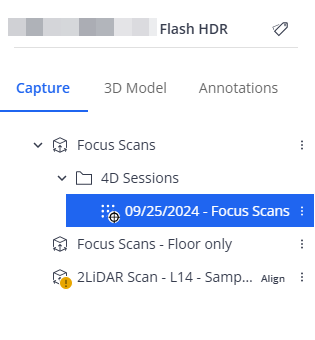
Figure 1-39 Project Structure View example
Sphere XG is subject to continuous development. Therefore, the information below may not be complete.
The header of the project structure view shows the project name and the Tag Management button ![]() .
.
Search: You an enter text to search for any object in the project structure view. The project structure view will only display objects that match the search. In the Viewer, objects that do not match the search will be grayed out. See Filter for Tags and Filter for the Time of Capture.
![]() : Opens the filter bar. This bar contains the Tags button and the Time of capture buttons. Clicking the Tags button opens a form that allows filtering for tags. Clicking the Time of capture button opens a form that allows filtering for capture dates.
: Opens the filter bar. This bar contains the Tags button and the Time of capture buttons. Clicking the Tags button opens a form that allows filtering for tags. Clicking the Time of capture button opens a form that allows filtering for capture dates.
![]() Area: An area is the physical representation of a location in your project, for example the first floor of a building, hangar A, etc. A project may have more than one area. Areas contain, scans, sheets, 360° photos, etc. They are shown with icon
Area: An area is the physical representation of a location in your project, for example the first floor of a building, hangar A, etc. A project may have more than one area. Areas contain, scans, sheets, 360° photos, etc. They are shown with icon ![]() in the project structure view. In HoloBuilder and the JobWalk App, areas are called sheets. When you import a document as new area, it is in the first place a spatial container but it is visually represented by the uploaded document, i.e. the sheet.
in the project structure view. In HoloBuilder and the JobWalk App, areas are called sheets. When you import a document as new area, it is in the first place a spatial container but it is visually represented by the uploaded document, i.e. the sheet.
Under this node, you find the scans and scan point clouds of a project. This can be scans which you have uploaded manually, for example .e57 and .cpe files as well as Stream and SCENE and Blink scans. On these scans, you can run registrations and synchronize them between Sphere XG and SCENE. See the SCENE user manual for more information.
Apart from the usual three dimensions, the time dimension is available via captures of the same location that were taken at different times. For example, this is helpful to watch the progress on a construction site. This time travel is also available as a dropdown list in the 2D view, the 3D view and the walk mode view if captures at different points of time are available.
![]() Scans of a project.
Scans of a project.
![]() Cluster of scans. These are groups of scans. Currently, you can only create clusters in Stream and in SCENE. If you see this icon
Cluster of scans. These are groups of scans. Currently, you can only create clusters in Stream and in SCENE. If you see this icon ![]() , it means that this cluster has been uploaded from SCENE and is locked. Note that locking and unlocking clusters is not possible in Sphere XG.
, it means that this cluster has been uploaded from SCENE and is locked. Note that locking and unlocking clusters is not possible in Sphere XG.
![]() Point cloud: A point cloud is a set of data points that represents an object in 3D form, from which dimensions can be extracted. For more information, see chapter Working with Projects and its subchapters.
Point cloud: A point cloud is a set of data points that represents an object in 3D form, from which dimensions can be extracted. For more information, see chapter Working with Projects and its subchapters.
![]() Mobile scan: A scan captured by a mobile scanning device and optionally a mobile scanning app, for example the Orbis scanner and the Stream app.
Mobile scan: A scan captured by a mobile scanning device and optionally a mobile scanning app, for example the Orbis scanner and the Stream app.
![]() Flash scan: For more information on Flash scans, see Flash Scans in the Orbis user manual.
Flash scan: For more information on Flash scans, see Flash Scans in the Orbis user manual.
![]() Waypoint with a 360° photo, i.e. static HoloBuilder captures, see Capture 360° photos and create tours with the JobWalk App.
Waypoint with a 360° photo, i.e. static HoloBuilder captures, see Capture 360° photos and create tours with the JobWalk App.
![]() 2D photo that was added in the HoloBuilder WebEditor with no assigned position.
2D photo that was added in the HoloBuilder WebEditor with no assigned position.
![]() Waypoint with a 360° photo and an additional 2D photo.
Waypoint with a 360° photo and an additional 2D photo.
![]() Location marker: These location markers are placeholders for images that should be added to the project.
Location marker: These location markers are placeholders for images that should be added to the project.
![]() VideoMode capture, see VideoMode - A short overview in the HoloBuilder Help Center.
VideoMode capture, see VideoMode - A short overview in the HoloBuilder Help Center.
The following additional icons may be displayed on top of one of the above-mentioned icons to provide more information:
![]() The element requires additional action. For example, this icon is displayed on a point cloud icon (
The element requires additional action. For example, this icon is displayed on a point cloud icon ( ) when the point cloud has not yet been aligned to the area. You can access the required information by clicking the three-dots icon
 ![]() to open the context menu.
to open the context menu.
![]() For point clouds imported manually, for example .cpe or .e57 files, this icon means that the cloud is either aligned or registered or was marked as georeferenced by the user.
For point clouds imported manually, for example .cpe or .e57 files, this icon means that the cloud is either aligned or registered or was marked as georeferenced by the user.
For point clouds uploaded from SCENE or created with the Blink workflow, this icon means that the point cloud is at its original position, and no further alignment has been applied in Sphere XG.
![]()
![]() Hide and show captures, e.g. waypoints, clusters and scans: Click the
Hide and show captures, e.g. waypoints, clusters and scans: Click the ![]() icon behind the element in the project structure view to hide them. The effect is different on waypoints and scans and also depends on the publishing time of the project. For more information, see .Clicking the icon (
icon behind the element in the project structure view to hide them. The effect is different on waypoints and scans and also depends on the publishing time of the project. For more information, see .Clicking the icon (![]() ) again, will display the hidden clusters and captures again.
) again, will display the hidden clusters and captures again.
Three-dots Menu
Depending on the element, the three-dots menu provides different options:
![]() Set area scale: ts the scale of an area, see Set the Scale of an Area.
Set area scale: ts the scale of an area, see Set the Scale of an Area.
![]() Align: Starts the alignment of one element to another, for example the aligning a point cloud to a 3D model. See section Align Point Clouds, 3D Models, Sheets and Areas for more information.
Align: Starts the alignment of one element to another, for example the aligning a point cloud to a 3D model. See section Align Point Clouds, 3D Models, Sheets and Areas for more information.
![]() Georeferencing: If the point cloud has not been aligned or registered, this option allows you to treat the point cloud as being within the coordinate system of the 3D model. To undo the georeferencing, select this option again. For already georeferenced point clouds, the option label is Reset to original position.
Georeferencing: If the point cloud has not been aligned or registered, this option allows you to treat the point cloud as being within the coordinate system of the 3D model. To undo the georeferencing, select this option again. For already georeferenced point clouds, the option label is Reset to original position.
![]() Download point cloud: Downloads the point cloud or the 3D model to your computer. If you want to export the point cloud in a specific format, see Export a Point Cloud or an Orthophoto with a Clipping Box.
Download point cloud: Downloads the point cloud or the 3D model to your computer. If you want to export the point cloud in a specific format, see Export a Point Cloud or an Orthophoto with a Clipping Box.
![]() Generate floor plan (beta): Generates a floor plan from a point cloud. See Generate a Floor Plan from a Point Cloud (beta)for more information.
Generate floor plan (beta): Generates a floor plan from a point cloud. See Generate a Floor Plan from a Point Cloud (beta)for more information.
![]() Move to different area: Moves a waypoint with a 2D photo, a waypoint with a 360° photo or a location marker to another area in the project. See Move Waypoints within an Area for more information.
Move to different area: Moves a waypoint with a 2D photo, a waypoint with a 360° photo or a location marker to another area in the project. See Move Waypoints within an Area for more information.
![]() Add 360° photo: Adds a 360° photo to the selected waypoint.
Add 360° photo: Adds a 360° photo to the selected waypoint.
![]() Edit: Allows editing the element name and in some cases also the time stamp. Note that this is not possible for all elements.
Edit: Allows editing the element name and in some cases also the time stamp. Note that this is not possible for all elements.
![]() Adjust Trajectory: VideoMode only. Opens a page on which you can adjust the VideoMode trajectory. See Adjust Misalignments in the VideoMode Trajectory for more information. For a how-to on working with the Adjust Trajectory Tool, see Adjust Misalignments in VideoMode Trajectories in Sphere XG in the Help Center.
Adjust Trajectory: VideoMode only. Opens a page on which you can adjust the VideoMode trajectory. See Adjust Misalignments in the VideoMode Trajectory for more information. For a how-to on working with the Adjust Trajectory Tool, see Adjust Misalignments in VideoMode Trajectories in Sphere XG in the Help Center.
![]() Delete: Deletes the element. Note that you cannot undo the deletion once it is confirmed.
Delete: Deletes the element. Note that you cannot undo the deletion once it is confirmed.
![]() Only Registration mode. Centers the view on the current selection.
Only Registration mode. Centers the view on the current selection.
Buttons
Edit scans: Clicking this button opens the draft view . If you are looking at a project that is currently being published, the toggle is marked with a red indicator dot.
Import data/Import scans: Click this button to import point clouds, 3D models, scans, areas or sheets into your project. For more information, see Import Data Sets.
